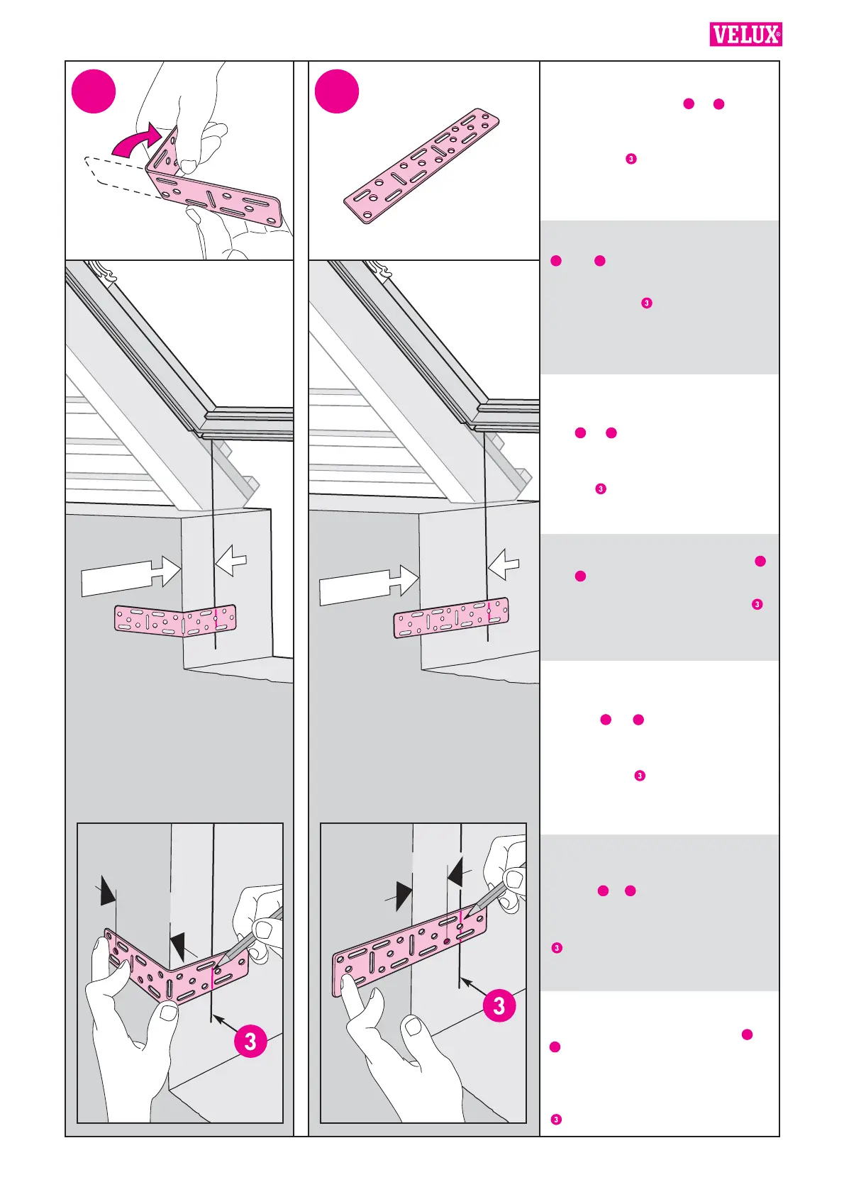
ENGLISH: Depending on the distance
X mm, the fixing brackets are positioned
as shown in illustrations or . Make
sure to observe the distance of min
60 mm from the corner to the first screw
hole (1). Transfer the vertical line
marked in ill. to the fixing brackets
(2).
DEUTSCH: Die Montagewinkel abhängig
vom Abstand X mm wie gezeigt in Abb.
oder platzieren. Den Abstand von
mindestens 60 mm von der Mauerecke
bis zum ersten Schraubenloch beachten
(1). Den in Abb. markierten senkrech-
ten Strich auf die Montagewinkel über-
tragen (2).
FRANÇAIS : En fonction de la cote
X mm, les pattes de fixation sont posi-
tionnées comme indiqué dans les sché-
mas ou . S’assurer qu’il y ait une
distance minimale de 60 mm du nu
intérieur au premier trou de vis (1).
Reporter la ligne verticale indiquée au
schéma sur les pattes de fixation (2).
DANSK: Afhængig af afstanden X mm
placeres beslaget som vist enten i ill.
eller . Afstanden på min. 60 mm til
første skruehul skal overholdes (1). Den
lodrette linie, der blev markeret i ill. ,
overføres til monteringsbeslagene (2).
NEDERLANDS: Afhankelijk van de af-
stand X mm, worden de bevestigings-
beugels bevestigd zoals getoond in de
illustratie of . Lees zeer secuur af of
de afstand van de hoek tot het eerste
gat daadwerkelijk min. 60 mm is (1).
Neem de verticale lijn, zoals gemar-
keerd als in ill. , over op de bevestig-
ingsbeugels (2).
ITALIANO: A seconda della distanza
X mm le staffe di fissaggio saranno
posizionate come mostrato nelle illu-
strazioni o . Assicurarsi di osser-
vare la distanza di almeno 60 mm tra
l’angolo e la prima vite (1). Trasferire la
linea verticale segnata nell’illustrazione
sulle staffe di fissaggio (2).
ESPAÑOL: Dependiendo de la medida
X mm, los herrajes de fijación se colo-
carán como se indica en la figura ú
. Asegúrese de que la medida desde
el borde hasta el primer orificio de
tornillo es como mínimo de 60 mm (1).
Marque en el herraje la linea de los la-
terales del hueco realizada en el paso
(2).
 Loading...