2019.10 12 / 31
Figure 5.4 Connection Schema
6. CONNECTIONS
6.1. DUCT CONNECTIONS
Return air, fresh air, exhaust air and supply air ducts should be fixed (connected) to the unit with flexible
connection. Required leak-proofing should be obtained in order to ensure desirable air flow. Having improper
(bad) unit – duct connections and wrong dimension, shape and duct fragments inside of the connection may
cause a turbinated air flow.
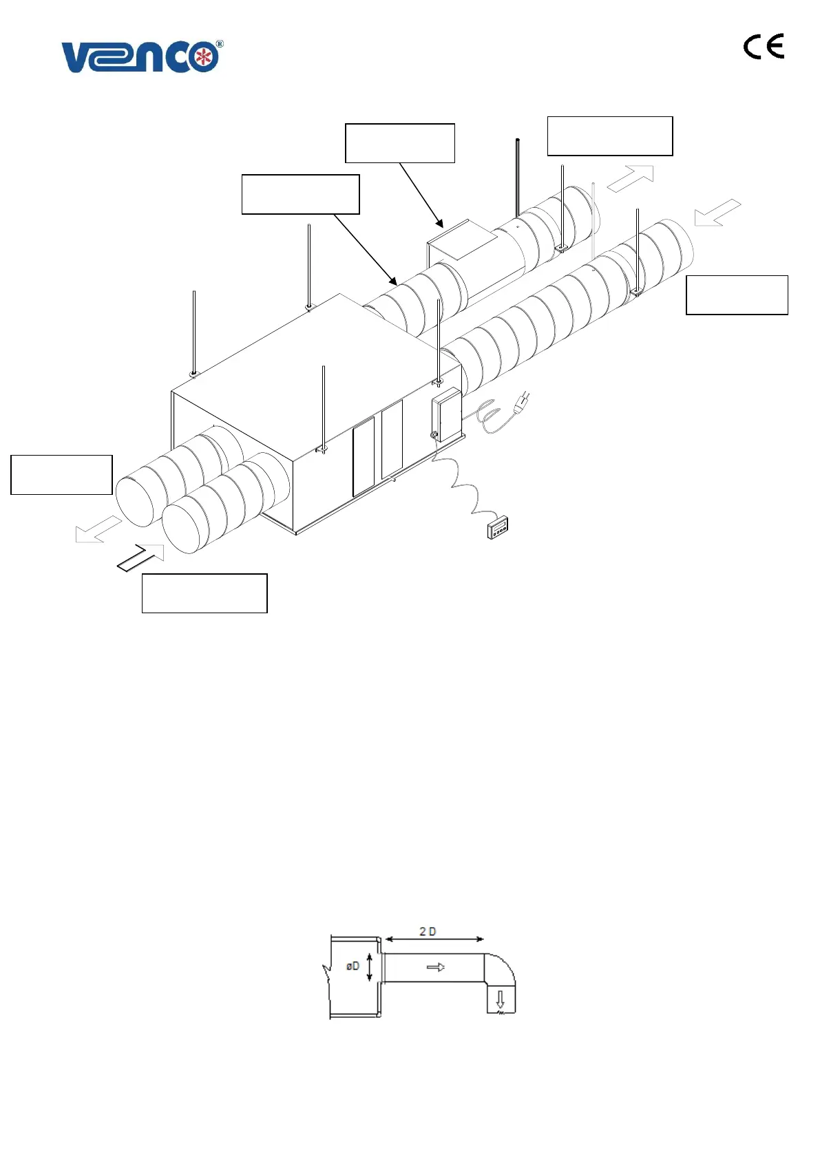
When air flow direction is changed at fan blowing outlet, excessive losses may occur. If this is compulsory,
connections should be done as Figure 6.1.1. The length of duct, before the elbow or electrical heater, should
be double of the outlet-diameter.
Figure 6.1.1. Duct Connections Schema (Changing the direction of air flow)
 Loading...