2019.10 2 / 31
Index
1. INTRODUCTION ..................................................................................................................................... 4
2. HEAT RECOVERY UNITS and VHR MODELS ....................................................................................... 4
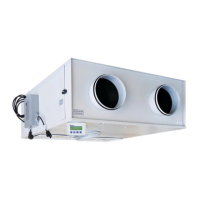
Figure 2.1. VENCO Heat Recovery Units .................................................................................................... 4
Figure 2.2. Heat Recovery Unit Schema ..................................................................................................... 5
Figure 2.3. Heat Recovery Unit Schema (Plug) ........................................................................................... 5
3. TECHNICAL SPECIFICATION for HEAT RECOVERY UNITS ................................................................ 6
Table 3.1.1 Technical Specifications for VHR Models ................................................................................. 6
Table 3.1.2 Technical Specifications for VHR EC Models ........................................................................... 7
Table 3.2. Dimensions for VHR and VHR EC Models ................................................................................. 8
4. WORKING CONDITIONS ..................................................................................................................... 10
5. TRANSPORTATION – STORAGE – INSTALLATION ........................................................................... 10
Figure 5.1. Lifting Schema ........................................................................................................................ 10
Figure 5.2. Installation Schema ................................................................................................................. 11
Figure 5.3. Connection Schema (Top View) .............................................................................................. 11
Figure 5.4 Connection Schema ................................................................................................................. 12
6. CONNECTIONS .................................................................................................................................... 12
6.1. DUCT CONNECTIONS ..................................................................................................................... 12
Figure 6.1.1. Duct Connections Schema (Changing the direction of air flow) ............................................ 12
6.2. DRAIN CONNECTIONS .................................................................................................................... 13
6.3. ELECTRICAL CONNECTIONS.......................................................................................................... 13
7. SAFETY REQUIREMENTS ................................................................................................................... 13
8. SAFETY LABELS .................................................................................................................................. 14
9. CONTROLS BEFORE START-UP ........................................................................................................ 15
10. TRAINING of TECHNICIANS ............................................................................................................. 16
11. RECOMMENDATIONS FOR SAFETY............................................................................................... 16
12. START-UP ......................................................................................................................................... 16
13. MAINTENANCE ................................................................................................................................. 16
14. CONTROL FUNCTIONS.................................................................................................................... 17
14.1. Standard Electronic Controller (SEC) ............................................................................................. 17
Figure 14.1.1. Standard Electronic Controller (SEC) ................................................................................. 17
Table 14.1.1. Electronic Controller Buttons ............................................................................................... 18
14.2. Functional Electronic Controller (FEC) ........................................................................................... 19

 Loading...