7. Weekly timer off: press TIMER OFF button, all the days display, then press this button to switch the
hour->minute->invalidation of timer. Users can set the hour and minute when flashing. When it shows
“--:--”; it means timer is invalid. Besides, users can press DAY button to switch the day, the day flashed
when chosen.
After setting, please press SET button to save the data or press EXIT to leave the operation without
saving the data. In the status of TIMER OFF, code “1” “2” stands for the first or second period of timer.
User can choose the period of timer by pressing the button of “MODE”. If no operation in 8 seconds,
display will disappear and all setting is invalid.
8. Check weekly timer: press DAY button, and press button ℃ and ℃ to choose the day, then the set
timer on and timer off will display. Users can press TIMER ON or TIMER OFF button to check the exact
time.
9. The running of weekly timer: the control system will record the current time, the ventilator starts to
run automatically when the timer is on, if the unit is on already, it maintains running. On the other
hand, it stops when the timer is off, if it is off already, it remains stop status. The timer on and off can
be used independently or simultaneously. When the timer is ON/OFF, users can still change the ON/OFF
status of the unit.
10. Parameter List of Controller are kept after restarting from power-off.
11. temperature setting, after connecting the electrical heater to the PCB (LD3 and LD4), then can set
the temperature by temperature increase and decrease buttons, when SA temperature lower than set-
ting temperature then electrical heater on
1) 0℃<setting temperature - SA temperature<5 ℃,1st stage heater on, 2nd stage heater off
2) Setting temperature - SA temperature >5℃,1st and 2nd stage heater on
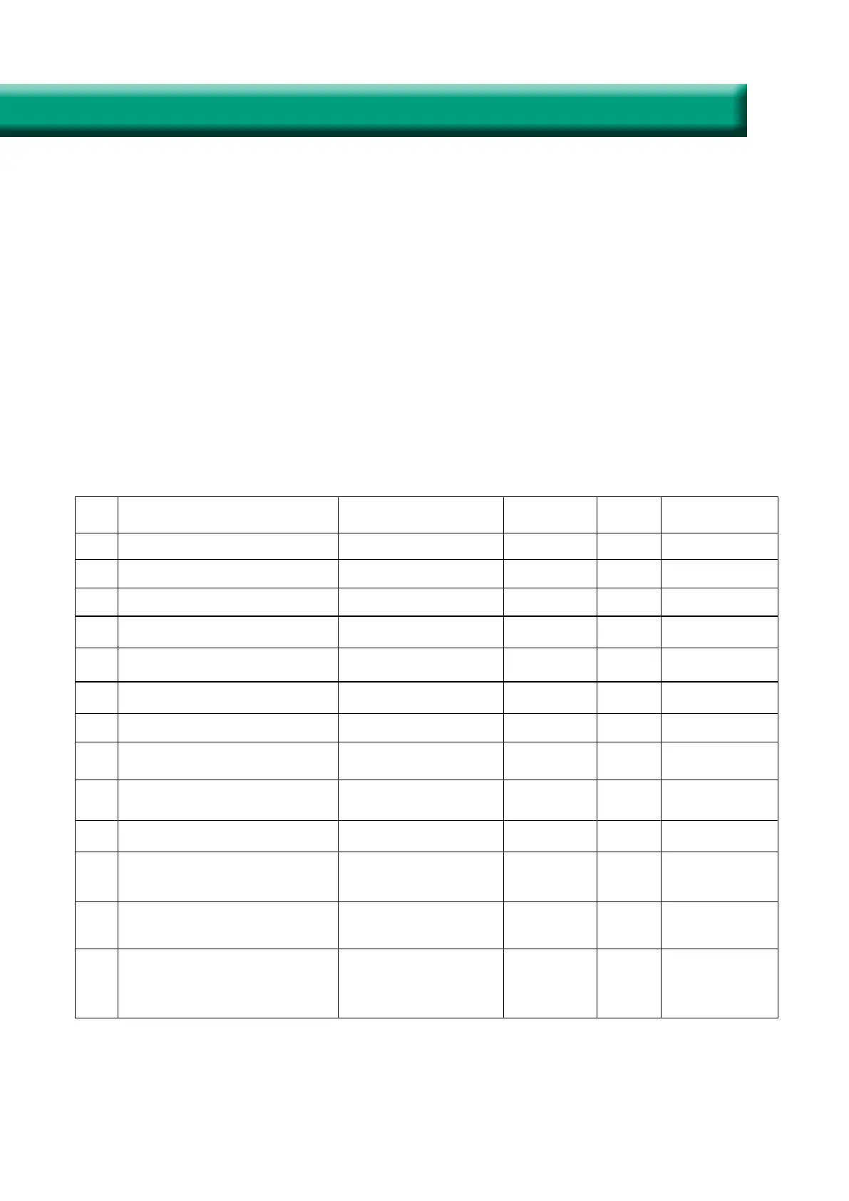
No. Contents Range Default Record Position Unit
00 Power to auto restart 0-1 1 Main control
01 Electrical heater available 0-1 0 Main control
02 Bypass opening temperature X 5-30 19 Main control
℃
03 Bypass opening temperature
range Y
2-15 3 Main control
℃
04 Defrosting interval 15-99 30 Main control Minute
05 Defrosting entering tempera-
ture
-9-5 - 1 Main control
℃
06 Defrosting duration time 2-20 10 Main control Minute
07 CO2 sensor function value 28-C8
(392-1960PPM)
66
(1000PPM)
Main control PPM
08 ModBus address 1-16 1 Main control
21 ERV models match/selection 0-7 0 Main control
23 Fan speed control 0: 2 speeds
1: 3 speeds
2: 10 speeds (DC)
1
24 Multifunction setting 0: Reserved
1: Sweep filter alarm
2: sweep weekly timer
0
25 Filter alarm setting 0: 45 days
1: 60 days
2: 90 days
3: 180 days
0 Main control
18
Intelligent Controller Instruction
 Loading...