10
EN
The fan mounting sequence is shown in Fig. 4-11.
The fan wiring diagrams are shown in Fig. 12-14.
Terminal designations on the wiring diagrams
L : line
S
: external switch
N : neutral
QF
: double pole circuit breaker
LT: timer control line
WARNING! The power cable may only be laid through the hole in the casing provided by the manufacturer.
Laying the power cable through a manually drilled hole will not be the liability of the manufacturer and will void
the warranty. The wires must be stripped of insulation by a maximum of 8 mm.
After installation, pass this User’s manual to the end user for reading.
1
2
2250
750
750
600
600
R 600
1
2
3
1
1
3
3
2
2
2
2
1
2
2
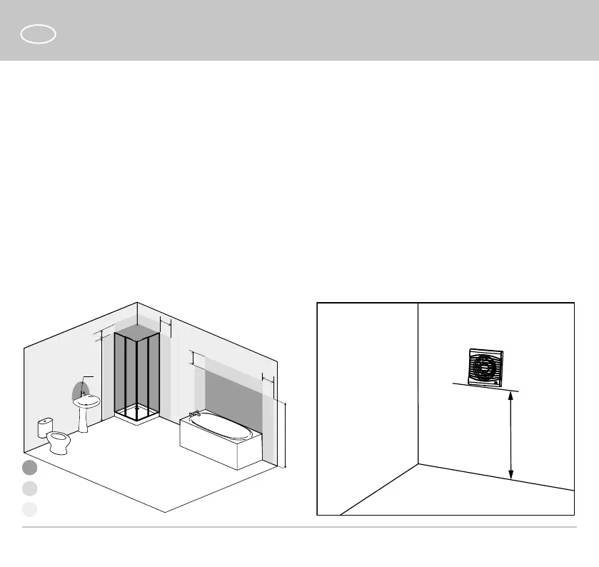
The unit with a protection rating against access to hazardous
parts and water ingress IP34 is allowed to be installed in zone
2, according to IEC 60364-7-701:2019.
min. 2.3 m
CAUTION! The unit must be installed at a distance of
at least 2.3 m from the oor.
 Loading...