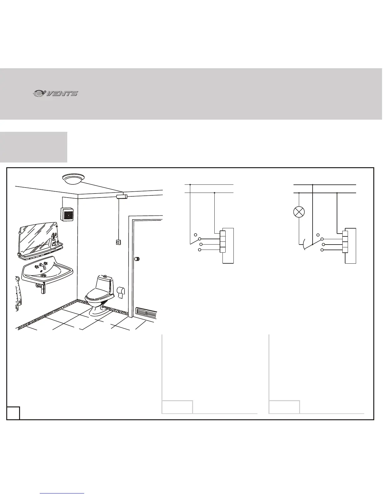
Sample schematic of basic three-speed fan model connection - basic modification and
modification C.
65
Diagram 1 Diagram 2
3
3
1
N
L
N
1
A
S
2
2
EL
3
3
1
N
2
S
OFF
2
L
N
1
OFF
A
EL
B
A
S
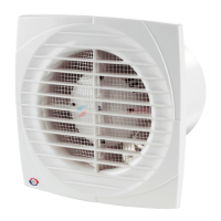
A - Fan
B - Distribution box
EL - Lighting lamp
S - External speed switch
P3-1-300 (shown schematically).
The fan is set to one of the three speeds
as necessary or switched off manually
with the help of external switch S
(e.g. P3-1-300).
The fan is set to one of the 3 speeds with
the help of the external switch S
(e.g. P3-1-300).
The fan is activated or deactivated
simultaneously with the light in the
premises.
The fan is activated / deactivated only
simultaneously with the lights.
FAN CONNECTION
TO POWER MAINS
SCHEMATICS
30
VNVN
 Loading...