9
INSTALLATION
AND SETUP
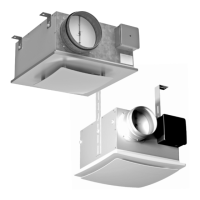
The fan can be mounted on the ceiling or on a wall with the air exhaust directed into a
ventilation shaft or a round duct of suitable diameter.
Examples of fan installations are given on Fig. 12-22.
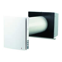
Examples of in-the-wall fan mounting with a supplementary inlet fitting are given on Fig. 23-24.
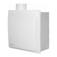
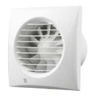
To install fan VN-1 80:
1.1. Mark and drill a hole for the outlet fitting following one of the 4 installation options (Fig. 25-28);
1.2. Remove the front panel (Fig. 29);
1.3. Remove the filter (Fig. 30);
1.4. Remove the screw and the grill (Fig. 31);
1.5.. Install the fan casing as shown (Fig.. 25-28), mark the holes for self-tapping screws (Fig. 32);
1.6. Drill dowel holes and install the dowels (Fig. 33);
1.7. Install the fan casing and scroll assembly and secure it with self-tapping screws (Fig. 34);
1.8. Perform operations 1.2.-1.4. in the reverse order.
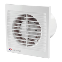
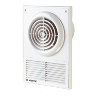
To install VN 80 fan:
2.1. Mark and drill a hole for the outlet fitting following one of the 4 installation options (Fig. 25-28);
2.2. Remove the decorative blind (Fig. 35);
2.3. Remove the front panel retention screw (Fig. 36);
2.4. Remove the front panel (Fig. 37);
2.5. Perform operations 1.6.-1.7.;
2.6. Perform operations 1.2.-1.4. in the reverse order.
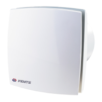
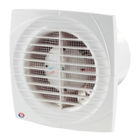
To install VN-1 80 Ê fan:
3.1. Mark and drill a hole for the outlet fitting following one of the 3 installation options (fig. 25-27);
3.2. Perform operations 1.2.-1.4.;
3.3. Set the hinged fire damper to the mounting position (Fig. 38);
3.4. Mark dowel hole centers (Fig. 39);
3.5. Drill dowel holes and install the dowels (Fig. 40);
3.6. Secure the hinged fire damper with self-tapping screws (Fig. 41);
VNVN