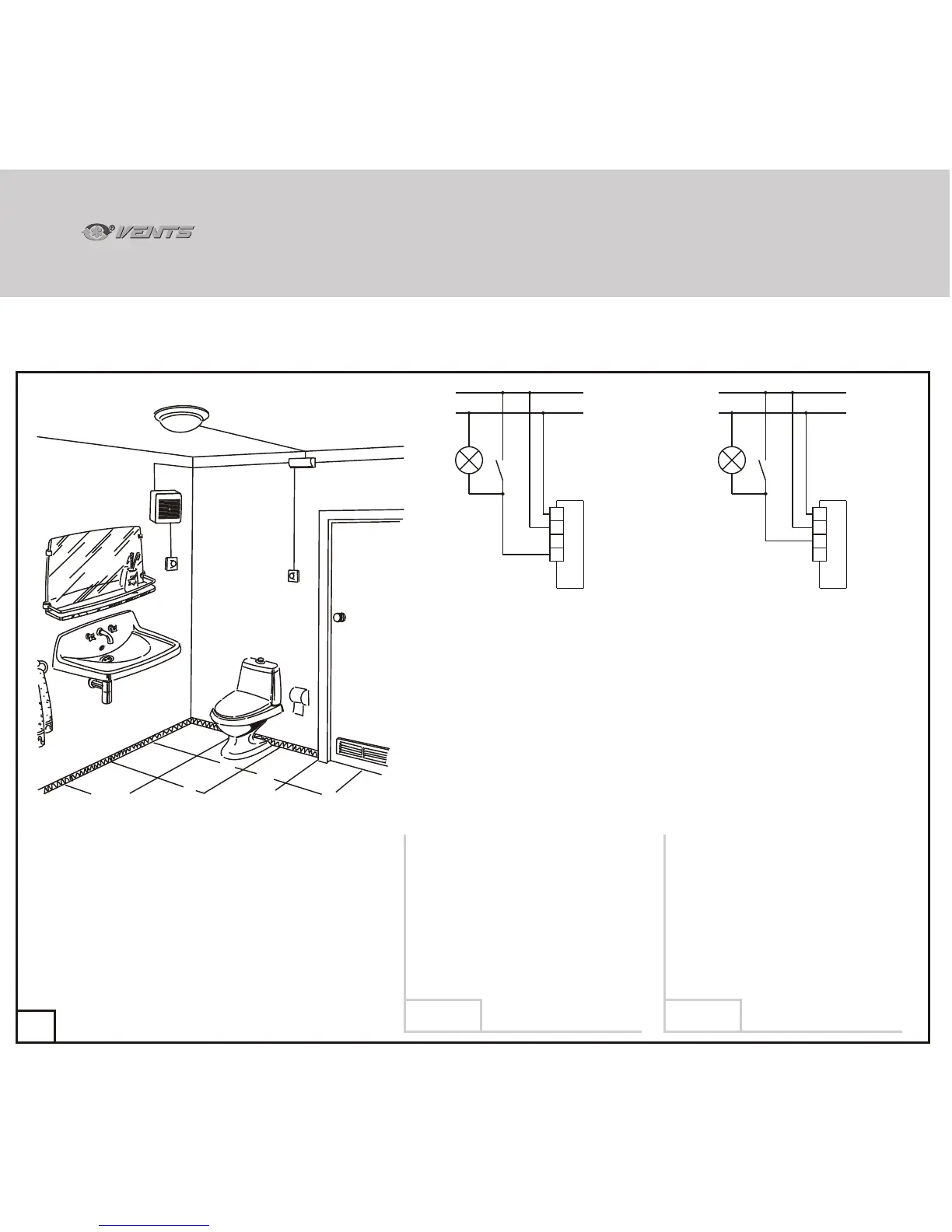
Sample schematic of basic two-speed fan model connection (modifications A, B and D) with a humidity sensor (H).
CONTINUED.
71
EL
B
A
S1
A - Fan
B - Distribution box
EL - Lighting lamp
S1 - lighting switch
(shown schematically)
SÂ - base load mode switch
(shown schematically).
SÂ
The fan constantly operates at speed 1 if
the lights are switched on (using switch S1)
or remains off is the lights are off.
As the relative humidity on the premises
increases the fan automatically switches to
speed 2 and maintains it until humidity
drops to the pre-set level irrespective of
switch S1 position.
The fan initial state is off.
As the relative humidity on the premises
increases the fan automatically switches to
speed 2 and maintains it until humidity
drops to the pre-set level.
You may use switch S1 which also doubles
as the light switch to manually engage
speed 2.
In this case speed 2 turn-on delay is
50 seconds. The turn-off delay following the
switch opening may range from
2 to 30 minutes (speed 1 is not used in this
operation pattern).
M
LT
N
S1
L
L
N
EL
A
M
LT
N
S1
L
L
N
EL
A
36
VNVN
Diagram 12Diagram 11
 Loading...