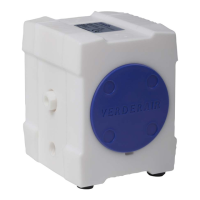
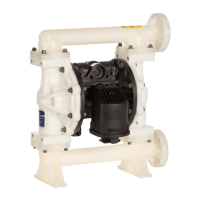
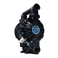
The Verderair Pure is an air-operated double diaphragm (AODD) pump designed for efficient fluid transfer. It is specifically engineered for high efficiency, making it a suitable choice for various industrial applications where reliable and economical pumping is required.
Function Description
The Verderair Pure pump operates on compressed air to create a reciprocating motion of two diaphragms, which in turn displaces the fluid. This design allows for the transfer of a wide range of liquids, including viscous, abrasive, and chemically aggressive fluids, without mechanical seals that could wear out or leak. The pump is self-priming and can run dry without damage, offering flexibility in installation and operation. It builds pressure at the liquid side up to the pressure set on the compressed air-inlet, and can stall against a closed discharge line without damage, automatically restarting when the liquid side pressure drops.
Important Technical Specifications
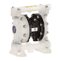
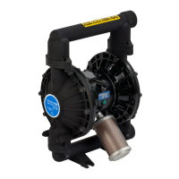
The Verderair Pure series comes in various sizes, indicated by their nominal port size, ranging from 1/4" to 2". The pump's construction materials, such as PE (Polyethylene) and PTFE (Polytetrafluoroethylene), are available in both standard and conductive versions, making them suitable for ATEX environments when conductive materials are used and properly grounded.
Weight (ISO measurements):
- VA-P08: PE1000: 1.1 kg, PTFE: 2.5 kg
- VA-P10: PE1000: 3.6 kg, PTFE: 5.1 kg
- VA-P15: PE1000: 6.9 kg, PTFE: 15.4 kg
- VA-P25: PE1000: 15 kg, PTFE: 34 kg
- VA-P40: PE1000: 39 kg, PTFE: 87 kg
- VA-P50: PE1000: 85 kg, PTFE: 193 kg
Max. Operating Pressure: 7 Bar (102 PSI) for all models.
Max. Operating Temperature:
- PE1000: 70°C (158°F)
- PTFE: 100°C (212°F) for VA-P08/10, 120°C (248°F) for VA-P15/25/40/50
Suction Lift (dry):
- Ball Valves: 0.5 to 4 mwc (1.6 to 13.1 feet wc) depending on model
- Cylinder Valves: 1 to 5 mwc (3.3 to 16.4 feet wc) depending on model
Suction Lift (wet): 9 to 9.5 mwc (29.5 to 31.2 feet wc) for all models.
Theoretical Displacement Volume (single stroke):
- VA-P08: 0.0075 liters (0.0002 US gallons)
- VA-P10: 0.0215 liters (0.0006 US gallons)
- VA-P15: 0.1 liters (0.0026 US gallons)
- VA-P25: 0.34 liters (0.0090 US gallons)
- VA-P40: 0.98 liters (0.0259 US gallons)
- VA-P50: 2.6 liters (0.0687 US gallons)
Max. Particle Size of Solids (for pumps with ball valves): 2.2 mm to 11 mm (0.09 to 0.43 inches) depending on model.
The pump's performance charts detail flow rate (GPM/l/min) against discharge pressure (bar/psi) for various air consumption rates (Nm³/min/SCFM), allowing users to select the optimal operating point for their application.
Usage Features
Installation:
- Mounting: The pump should be installed load-free to prevent damage. It comes with adjustable feet. The mounting surface must support the pump's weight, hoses, accessories, and operational stress.
- Air Line: Requires an air regulator and gauge to control driving air pressure. A bleed-type master air-valve is recommended if the regulator lacks a bleed-off function or is not close to the pump. A grounded, flexible air hose with an inner diameter equal to or larger than the pump's air connection is required. Clean, dry, and oil-free compressed air is essential for optimal air-valve performance; a dryer and/or water separator may be needed.
- Fluid Inlet/Outlet Ports: Suction and discharge connections are integrated into the center block, offering both horizontal and vertical porting options. Pumps are delivered with horizontal connections open and vertical connections plugged. Rotating the center housing 180° allows for other porting combinations.
- Suction Line: A shut-off valve should be installed before the pump. Flexible connections are recommended to avoid vibrations. The suction line must withstand vacuum, and its inner diameter should match the pump's connection diameter. Inlet pressure exceeding 25% of outlet working pressure can lead to inefficient operation and shortened diaphragm life.
- Fluid Outlet Line: A shut-off valve should be installed after the pump, and a drain valve is recommended to relieve pressure before maintenance. Flexible connections are also advised for the outlet line.
- Grounding: Essential for ATEX certified pumps (conductive PE and PTFE models) to prevent static and electric shock. A grounding connection is included in the center housing of conductive pumps. Regular checks of system electrical continuity are advised. Non-conductive pumps should never be used with non-conductive flammable fluids.
- Air Exhaust Ventilation: The exhaust port should not be restricted. Remote ventilation to a safe area is recommended, especially as pumped liquid can escape through the muffler in case of diaphragm rupture. Optional diaphragm monitoring and barrier chambers can prevent this.
Operation:
- Self-priming: VA-P pumps are dry self-priming and do not require filling before first use.
- Pressure Build-up: Pumps build pressure at the liquid side up to the compressed air-inlet pressure. A pressure relief valve or other safety equipment should be installed if this pressure exceeds the discharge line's rated pressure.
- Stall Capability: Pumps can stall against a closed discharge line without damage and will restart automatically when pressure drops.
- Starting and Adjusting: Ensure proper grounding and tight fittings. Slowly increase air pressure until the pump cycles, allowing it to prime and push air out of the lines.
- Flushing: The pump should be flushed with a neutral fluid before changing mediums or storing to prevent contamination, drying, or freezing.
- Submerged Operation: Possible if the air outlet is connected to the atmosphere via a flexible hose, and all external parts are resistant to the medium. The pump must remain 100% vertical and not float.
- Nitrogen Gas Operation: Can be run on nitrogen gas instead of compressed air, with adequate ventilation for exhaust.
Optional Equipment:
- Stroke Sensor (SS): Generates a pulse per complete stroke, connectable to a Namur inlet controller.
- Remote Operation (RE): Separate connections for external air signal control, without an air valve or muffler.
- Manual Draining (DM): Side housings with an integrated by-pass system for manual draining.
- Pneumatical Draining (DP): Side housings with a by-pass system for pneumatic signal-operated draining.
- Barrier System with Sensors (BS): Double diaphragms with a neutral medium in between, and sensors to detect diaphragm failure and trigger an alarm/stop.
- Leak Detection (LS): Capacitive sensor in the muffler detects liquid from diaphragm rupture. Note: humid air can cause false fault signals.
- Prepared for Dampener (PD): Center housing mounted with vertical connection upwards for pulsation dampener installation (dampeners not included).
- Combination Options: MD (DM+PD), SL (SS+LS).
- ANSI Prepared (AP): Flange holes drilled to ANSI standards (no inserts).
- Vertical Suction (VS): Center plug mounted on the horizontal suction connection.
Maintenance Features
Preventive Maintenance Schedule:
- Establish a schedule based on pump service history to prevent spills or leakage from diaphragm failure.
Tightening Fasteners:
- Before initial use, after the first day of operation, after temperature fluctuations, transport, or dismantling, check and retorque housing bolts (23), discharge valve stops (09), and plugs (04) according to specified torque values (page 22).
Disassembly and Assembly:
- Safety First: Always follow the Pressure Relief Procedure (page 10) before working on the pump. After a diaphragm rupture, ensure no liquid remains on the air side, especially in the muffler (07).
- Tools: Each Verderair Pure pump comes with a special tool for disassembling the air valve (27) and liquid plugs (09) and center housing plug (04).
- Valve Seats and Balls: Access by unscrewing the liquid plug (09) with the special tool. Remove the spacer (13), valve ball (11) or cylindrical valve (10), and valve seat (12).
- Side Housings: Remove covers (08) by gently pushing with a screwdriver. Unscrew bolts on assembly pins (23), remove washers and spring washers, then remove side housings (02-03). Be careful not to damage sealing surfaces. Remove housing o-rings (22).
- Diaphragms and Diaphragm Shaft: Unscrew one diaphragm (17) (left turning) from the diaphragm shaft (19*). Pull the shaft with the second diaphragm out of the center housing (01) and unscrew the second diaphragm. For VA-P08 and VA-P10, the diaphragm shaft is part of the air-valve (27).
- Center Housing (VA-P15 to VA-P50): Carefully remove diaphragm shaft bearings and o-rings (20) from their grooves.
- Air Valve: Unscrew the muffler (07) and air inlet connector (05). Use the special tool for the center housing plug (04) and both end caps of the air valve (27). Push out the main-valve and air valve shaft, then the air-valve housing.
- Assembly Checks: Before assembly, check all parts for damage, especially sealing areas.
- Assembly Steps:
- Center Housing: Remove end caps, main-valve, and air valve shaft from the air-valve (27). Screw one end cap flush into the center housing (01). Place one air-valve housing o-ring (part of 27) into the end cap. Push the air-valve housing into the center housing until it touches the end cap, ensuring the four o-rings are seated. Push the main-valve and air valve shaft into the center housing. Place the last air-valve housing o-ring on top and screw the second end cap flush. Screw the center housing plug (04), muffler (07), and air inlet connector (05) into the center housing.
- Diaphragm Shaft O-rings (VA-P15 to VA-P50): Place o-rings (20) into the center housing groove using locking ring pliers.
- Diaphragms and Diaphragm Shaft: Screw diaphragm shaft screws (18) into diaphragms and tighten. Screw one diaphragm (17) completely onto the diaphragm shaft (19). Push the shaft into the center housing (01) and screw the second diaphragm (17) completely onto the shaft (19). Adjust diaphragm position for assembly pins if necessary.
- Side Housings: Push side housing o-rings (22) into side housings (02-03). Push valve stops (15) into seats and lock with valve stop screws. Push assembly pins (23) through one side housing. Push center housing (01) over assembly pins, then the second side housing, ensuring washers and spring washers are correctly positioned.
- Final Assembly: Put washers and spring washers on assembly pins and fasten bolts crosswise to specified torque. Push side housing caps (08) onto side housings.
- Valve Seats and Balls: Place valve ball (11) or cylindrical valve (10) on valve seat (12). Push seat into side housing (02-03) at discharge side until it touches bottom. Push spacer (13) into side housing with side hole in contact with housing hole. Put liquid valve plug o-ring (14) on liquid valve plug (09) and screw plug flush into housing using special tool.
- Leakage Test: Always test the pump for leakages before using it.
Troubleshooting:
The manual provides a comprehensive troubleshooting guide, linking common problems (e.g., pump cycles at stall, erratic operation, air bubbles in fluid, insufficient discharge pressure) to potential causes (e.g., worn check valves, dirty air valve, clogged lines, diaphragm rupture, cavitation) and offering corresponding solutions (e.g., replace worn parts, clean air valve, check air supply, tighten connections, fill container).