1: Overview
6 Verint Video Solutions
S1708e and S1708e-AS
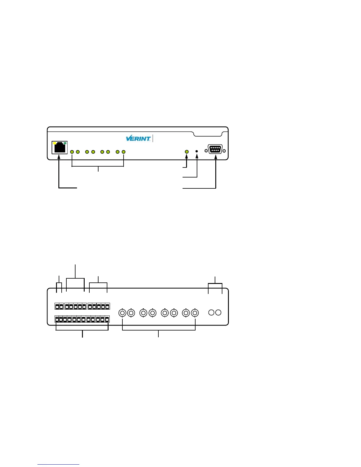
The front panel consists of:
An RJ-45 jack
Eight video status LEDs
A system status LED
A reset button
A DB-9 connector for the RS-232 serial port
Two versions of the back panels exist, since the device can have 1 or 12 audio inputs. The
back panel of the single-audio-input version consists of:
A 12-pole connector for input power, relay outputs, and RS-422/485 serial port
A 12-pole connector for dry contact inputs
Eight BNC connectors for video input
An optional set of 1/8 inch (3.5 mm) I/O audio connectors
RS232
ResetStatus
LAN 10/100
Video Status
18765432
S1708e
Nextiva
TM
RJ-45 Ethernet
System status
Reset
RS-232
Video status
IN
AUDIO
OUT
IN8
IN1 IN2 IN3 IN4 IN5 IN6
IN7
VIDEO IN
1
2
12
7
3
6
5
4
8
11
10
9
+12V
GND
RX-
RLY1
GND
RLY1
RLY2
RLY2
GND
RX+
TX-
TX+
12V DC
Dry contact input
RS-422/485 Audio (optional)
Video input
Relay output
 Loading...