Do you have a question about the Vertex FTL-7011 and is the answer not in the manual?
States that there are no user-serviceable points inside the transceiver and all service jobs must be referred to an authorized center.
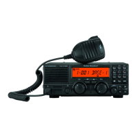
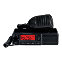
Details the FTL-1011, FTL-2011, and FTL-7011 FM transceivers, their capabilities, and design.
Details the Microphone Jack, MON Button & Indicator, and A (Accessory) Button & Indicator.
Covers Volume/Power Knob, BUSY/TX Indicator, Channel Controls, Display, and Scan/Priority Buttons.
Details the 13.6VDC Cable Pigtail, Antenna Socket, and External Speaker (EXT SP) jack.
Guide to turning on the radio, channel selection, and initial display indicators.
Explains CTCSS/DCS squelch, using the MON button for quiet reception or noise.
Details setting volume, proper transmitting procedure, and scanning modes for 12-channel versions.
Explains different scan modes (Sc, Ur, SP, UP) and the P/E indicators on the display.
Instructions for programming channels for scanning and priority monitoring.
Step-by-step guide for mounting the transceiver bracket and microphone hanger in a vehicle.
Details base station setup with FP-711 AC Power Supply and power connection precautions.
Provides instructions for connecting the DC power cable to the transceiver and battery terminals.
Advice on cleaning, protecting the radio, and recommending periodic dealer checks.
Guidance on replacing fuses and troubleshooting basic operational failures.
Lists frequency range, channels, mode, voltage, temperature, size, and weight.
Details receiver circuit type, sensitivity, selectivity, and transmitter power output.
Lists included accessories like microphone and bracket, and optional items like software and units.
| IP Rating | IP54 |
|---|---|
| Power Output | 5W |
| Channel Spacing | 12.5/25 kHz |
| Modulation | FM |
| Battery Type | Li-Ion |