Do you have a question about the Vertex evx-534 and is the answer not in the manual?
Procedure to confirm the VCO status (Lock/Unlock) for receive and transmit.
Procedure to align the reference frequency for the Phase Locked Loop.
Procedure to align the RX Band Pass Filter for optimal receive sensitivity.
Steps for aligning various squelch threshold and RSSI levels.
Procedure to align the output power levels (High, Low3, Low2, Low1).
Procedure to align the maximum frequency deviation for wide and narrow modes.
Procedure to align the digital mode deviation for symbol transmission.
Procedure to align the modulation balance for wide and narrow modes.
Procedure to align CTCSS deviation for wide and narrow bandwidths.
Procedure to align DCS deviation for wide and narrow bandwidths.
Procedure to align DTMF deviation levels.
Procedure to align MSK deviation for ANI operations.
Procedure to fine-tune sequential tone deviation for 2-Tone and 5-Tone encoding.
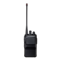
| Power Output | 5W (VHF), 4W (UHF) |
|---|---|
| IP Rating | IP57 |
| Digital Protocol | DMR |
| Waterproof | Yes, IP57 |
| Frequency Range | VHF: 136-174 MHz, UHF: 403-470 MHz |
| Zones | 32 |
| Signaling | DTMF, 2-Tone, 5-Tone |
| Channels | 512 channels |
| Battery Life | 11.7 hours (Digital), 8.6 hours (Analog) with FNB-V133LI battery |