VX-2100/-2200
(
VHF
)
Service Manual 1
VHF FM Transceiver
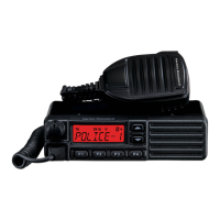
VX-2100
Series
VX-2200
Series
Service Manual
Specifications ............................................................... 2
DSUB 15-pin Accessory Connector .......................... 4
Exploded View & Miscellaneous Parts ................... 5
Parts List ........................................................................ 6
Block Diagram .............................................................. 7
Circuit Description ...................................................... 8
Alignment ................................................................... 10
Installation of Option ............................................... 16
Introduction
This manual provides the technical information necessary for servicing the VX-2100/-2200 Series Mobile Transceiver.
Servicing this equipment requires expertise in handing surface-mount chip components. Attempts by non-qualified
persons to service this equipment may result in permanent damage not covered by the warranty, and may be illegal
in some countries.
Two PCB layout diagrams are provided for each double-sided board in this transceiver. Each side of the board is
referred to by the type of the majority of components installed on that side (“Side A” or “Side B”). In most cases one
side has only chip components (surface-mount devices), and the other has either a mixture of both chip and leaded
components (trimmers, coils, electrolytic capacitors, ICs, etc.), or leaded components only.
As described in the pages to follow, the advanced microprocessor design of the VX-2100/-2200 allows a complete
alignment of this transceiver to be performed without opening the case of the radio; all adjustments can be performed
from the personal computer, using with the Vertex Standard FIF-12 USB Programming Interface and CE82 Software.
While we believe the information in this manual to be correct, Vertex Standard assumes no liability for damage that
may occur as a result of typographical or other errors that may be present. Your cooperation in pointing out any
inconsistencies in the technical information would be appreciated.
Board Units (Schematics & Parts Layout)
MAIN Unit ............................................................. 17
MAIN-2 Unit (50 W: Lot. 33~96) ......................... 35
FRONT-A Unit
(
VX-2100
)
.................................... 38
FRONT-B Unit
(
VX-2200
)
.................................... 40
Optional Units (Schematics & Parts Layout)
FVP-25 Encryption/DTMF Pager Unit ............... 42
FVP-36 Voice Inversion Type Encryption Unit ....
43
VX-2200
Series
VX-2100
Series
Important Note
This transceiver is assembled using Pb (lead) free solder, based on the RoHS specification.
Only lead-free solder (Alloy Composition: Sn-3.0Ag-0.5Cu) should be used for repairs performed on this ap-
paratus. The solder stated above utilizes the alloy composition required for compliance with the lead-free
specification, and any solder with the above alloy composition may be used.
Vertex Standard LMR, Inc.
©
2015 Vertex Standard LMR, Inc.
EC061N90M
Contents