VX-2100/-2200
(
VHF
)
Service Manual 11
Alignment
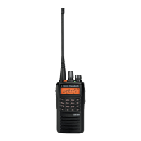
Test Setup
Setup the test equipment as shown below, and then ap-
ply 13.6V DC power to the transceiver.
The Alignment Tool Outline
Installation the tool
Install the CE82 (Clone Editor) to your PC.
The re-alignment for VX-2200/-2100 series may use the
“Alignment” menu of CE82.
Action of the switches
When the transceiver is in alignment mode, the action of
PTT and KEY is ignored. All of the action is remote con-
trolled by PC.
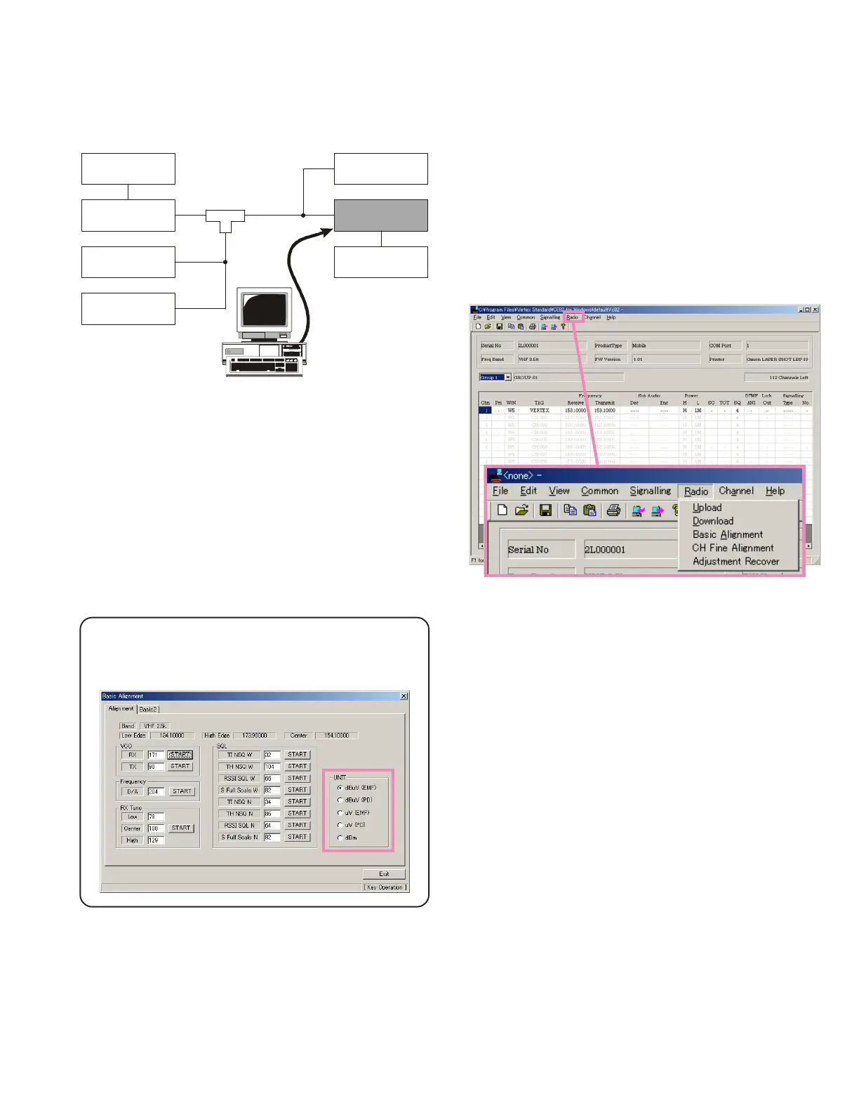
Basic Alignment Mode
The Basic Alignment mode allows you to align the entire
radio. The value of each parameter can be changed to the
desired position by use of the “
” / “
” and up/down
arrow keys, along with direct number input and drag-
ging of the PC mouse.
To enter the Basic Alignment Mode, select “Basic Align-
ment” in the main “Radio” menu. It will start to “Upload”
the written personalized data from the radio. Pressing the
“OK” button will then start the Basic Alignment Mode.
Note: when all items are to be aligned, it is strongly rec-
ommended to align them according to following sequence.
When the item is selected with TAB key, and the F1 key is
pushed, the “Help” file is displayed.
Detailed information for each step may be found in the
“Help” file within CE82 (Clone Editor).
1. RX VCO Tune Voltage (RX VCO)
2. TX VCO Tune Voltage (TX VCO)
3. PLL Reference Frequency (Frequency)
4. RX Sensitivity (RX Tune)
5. Squelch (SQL)
6. TX Power
7. Maximum Deviation <Wide> / <Narrow>
8. Sub Audio Deviation <CTCSS> / <DCS>
9. Sequential Tone Deviation
Transceiver
Inline
Wattmeter
Power Supply
13.6 VDC
Deviation Meter
Frequency
Counter
RF
Signal Generator
50-ohm
Dummy Load
MIC
USB Jack
ANT
RF Sampling
Coupler
DC INPUT
FIF-12
USB Programming Interface
Unit
During alignment, the values of dBμV or μV (EMF
or PD) can be selected or dBm.
 Loading...