10
procedure.
Manual control allows the user to manually drive the output percentage from 0.0 to
100.0%. To access the manual mode, set the “ ”parameter to “ ”, the rightmost
decimal (MA) on SV display will flash. Then the “ ” parameter will display alternately ”
” and process value. The output percentage then can be adjusted by pressing UP or
DOWN key. To abort the manual control just simply set the “ ” to “ ”.
2.1. HEAT / COOL USING THE ALARM
1. When it is required to have “Heat” and “Cooling” as for example on an extrusion barrel, you
can use the alarm setting as the “cooling setpoint”.
2. The alarm based cooling will be on/off and not proportional.
3. This in itself is not bad, as if you are cooling using a fan, or in other applications you may
have compressor cooling, you cannot use proportional control, as switching a fan motor or
compressor “on and off” rapidly will burn it out in any case.
4. In the case of liquid cooling (solenoid) on extrusion barrel zones, this method works just as
well as proportional.
5. You can however have a second output (optional extra) that will provide full PID control on a
second output and use it on a solenoid liquid cooling system should you so require.
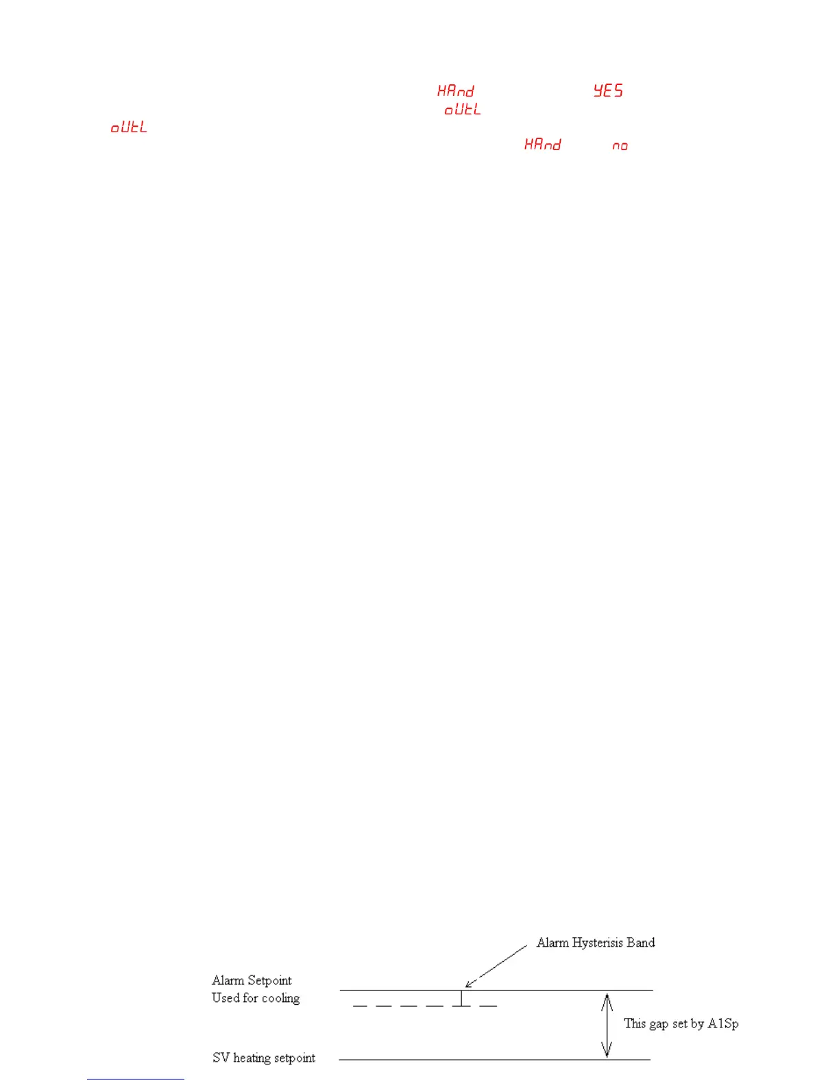
6. When using the “alarm” for cooling, you can set the gap between the heating and cooling
setpoints, and also specify how long the cooling must stay on each time it switches on using
the “hysteresis” adjustment.
7. When using the alarm for cooling, the first thing to do is select the “Alarm Function” that links
the alarm to the setpoint by a fixed “Gap”. You will find on your unit that the factory default is
set to this so it is not necessary to change anything. That is Alarm Function “diF.H”
(Deviation alarm high) selected in “oPt 1” level. The VT26 series controllers are supplied
with this as a default setting.
8. This means that the Alarm setpoint will be linked to the main (Heating) setpoint by a gap as
shown below.
9. When you move the main setpoint (Heating Setpoint) the Alarm (Cooling Setpoint) will follow,
always offset by the gap.
10. Once you have selected this function you now set the gap.
11. This is done in Level 1 using the “A1Sp” setting. This will be the amount of degrees C that
the Alarm Setpoint (Cooling Setpoint) will be above the Main Setpoint (Heating Setpoint)
12. You can now set the ‘Hysterisis” band attached to the alarm setpoint that will determine how
long the cooling stays on each time it is switched on.
13. The temperature must rise to the alarm setpoint which in this case will be the main setpoint
+ the alarm 1 setpoint before the alarm (cooling) will switch on.
14. It will now stay on until the temperature has dropped below the lower limit of the hysteresis
band before the cooling will switch off.
15. This setting is set in degrees C