12
Auxiliary Power Source
A 24 Vdc 40 mA auxiliary power source is available to drive 4 wire input devices
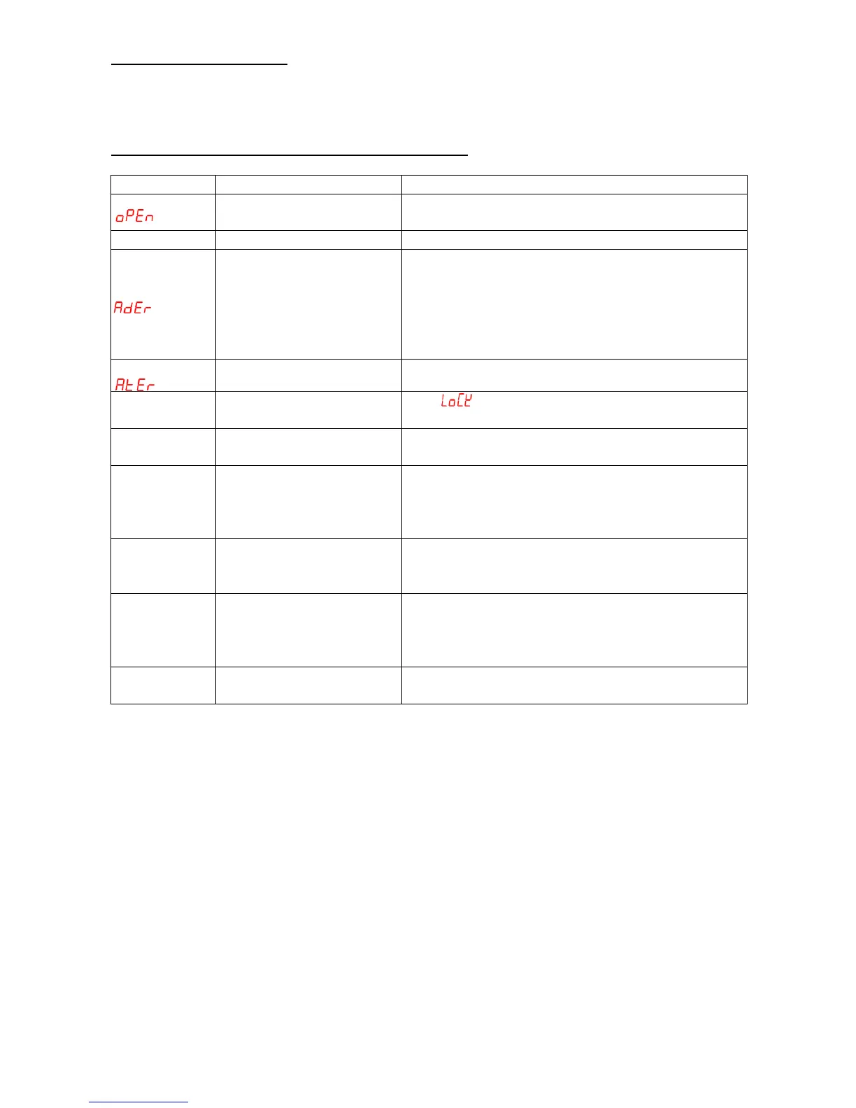
■ ERROR MESSAGE AND TROUBLESHOOTING
VERTEX 10/2016
VERTEX is constantly striving to improve its high-quality products, the information
contained in this manual is subject to change without notice. Every precaution has been
taken in the preparation of this manual
-Sensor break error
-Sensor not connected
-Replace sensor
-Check the sensor is connected correctly
-Unit must be repaired or replaced.
-Check for outside source of damage such as
transient voltage spikes.
-If the wires are connected back to front, at first
you will simply get a negative reading then when
it goes out of range the ader error.
-Auto tune time out error
-Keypads are locked
-Keypads defective
-Set” ”to a proper value
-Replace keypads
-Improper setting of Pb,
Ti, Td and CT
-Start AT process to set Pb, Ti, Td automatically
-Set Pb, Ti, Td manually
-No heater power or fuse
open
-Output device defective
or incorrect output used
-Check output wiring and fuse
-Replace output device
All LED’s and
display not
light
-No power to controller
-SMPS failure
-Check power lines connection
-Replace SMPS
Process Value
changed
abnormally
-Electromagnetic
Interference (EMI) or
Radio Frequency
Interference (RFI)
-Suppress arcing contacts in system to eliminate
high voltage spike sources. Separate sensor
and controller wiring from “dirty” power lines.
Ground heaters
-Fail to enter data to
EEPROM