EasyManua.ls Logo

Vertex VT4826+ User Manual

Vertex VT4826+
12 pages
To Next Page IconTo Next Page
Page #1 background imageLoading...
Page #1 background image
1
1. INTRODUCTION
This manual contains information for the installation, operation and tuning of your Vertex
VT26+ series FUZZY ENHANCED auto-tuning microprocessor based controller. These
controllers carry a two-year factory warranty. The VERTEX microprocessor controllers are
FUZZY ENHANCED “proportional + integral + derivative” (PID) controllers that come in a
variety of standard DIN sizes. The input is configurable and allows selection of inputs between
thermocouples and RTD’s. You can also have 4~20 and other linear inputs as an option to be
specified when ordering the controller. When ordering your controller you can choose between
Relay, SSR, Heat / Cool, 4~20 mA or other output signals. They have dual displays that show
the input (measured temperature) in the top digital display and the required set point in the lower.
They all come standard with 2 alarm relay outputs. The controller boasts a comprehensive range
of other features that include a ramp, soft start with power limiting, auto/manual function and
comes standard with two configurable alarms. The controllers can be switched to manual and
can work as “time based ratio out-put controllers” in the event of thermocouple or input failures
taking place. There are other options you can choose including “retransmission” of either the PV
or SV or RS485 communications.
Features:
T/C, RTD selectable from front panel or as optional extra Linear Input.
Heating output Relay, SSR or analog to be chosen when ordering
Fuzzy enhanced PID Control.
Auto / Manual Bumpless Transfer.
Two alarm outputs.
Standby and Latch mode can be combined with 8 different alarm functions.
Ramp to set point and soak functions.
Soft- start function.
Universal power supply : 100~240VAC, 50/60Hz. Or as optional extra 24
Vdc/Vac
PV or SV Retransmission (Cannot have retransmission and Cooling output
together.
RS-485 communication port as optional extra.(MODBUS RTU)
Input sampling time 0.1 sec
2. IN A HURRY
These Vertex temperature controllers, although quiet sophisticated, can be equally very
simple to use. In its simplest form, all you need to do is install it and get the wiring right,
(YOU MUST READ CONNECTIONS AND WIRING section) turn it on, check that the
thermocouple type it is correct, (during the self test it will display the input type), make
sure it is reading more or less the right temperature, that the heating elements actually get
hot when the “C1” light is on and away you go. No need for laboriously reading this
manual and changing and setting all the parameters….Just turn it on and when the system
INSTRUCTION MANUAL FOR
VT48/96/72… 26+ FUZZY PID
Question and Answer IconNeed help?

Do you have a question about the Vertex VT4826+ and is the answer not in the manual?

Vertex VT4826+ Specifications

General IconGeneral
BrandVertex
ModelVT4826+
CategoryController
LanguageEnglish

Summary

1. INTRODUCTION

Product Features Overview

Summarizes key features of the Vertex VT26+ series fuzzy enhanced PID controllers.

2. QUICK START GUIDE

Front Panel Description

Display Elements and Indicators

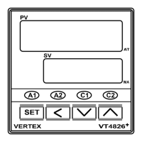
Details the Process Value (PV), Setting Value (SV), and various indicator LEDs on the controller's front panel.

Front Panel Control Keys

Explains the function and operation of the SET, UP, DOWN, and SHIFT control keys.

Hardware Specifications and Wiring

Model Dimensions and Panel Cutout

Provides physical dimensions for VT4826+ models and the required panel cutout specifications.

Wiring Precautions and Connections

Offers essential precautions for wiring and explains connection symbols for input/output signals.

Programming Level Parameters

Parameter Level Navigation

Outlines the structure and access methods for different programming levels (1st to 5th).

Parameter Descriptions: User and Soft Levels

Level Selection and User Parameters

Details how to access levels and describes User Level parameters like SP, A1SP, and At.

Soft Start Parameters

Explains parameters related to the soft-start function, including ramp rate and output percentage.

Parameter Descriptions: PID and Other Levels

PID Level Parameters

Covers key PID parameters such as Proportional Band (Pb), Integral Time (ti), and Derivative Time (td).

Control and Hysteresis Parameters

Describes parameters for secondary control, hysteresis, dead band, set point offset, and parameter locking.

Option Level Parameters: Input and Output

Input Type and Unit Configuration

Details input type selection (T/C, RTD, Linear) and unit configuration (C, F, Engineer).

Output Action and Span Settings

Explains output control action (ACE) and span limits (LoLt, HILE) for controller configuration.

Filter, Timer, and Alarm Functions

Describes software filter, timer settings for alarms, and alarm function selections (AIFU, A ind).

Option Level Parameters: Alarms and Scaling

Alarm Mode and Communication Settings

Covers Alarm 2 mode (A2nd), controller address (Addr), baud rate (bAUd), and linear input scaling (LnLo, LnHi).

Alarm Function Definitions

Provides detailed definitions for various alarm functions like Hi, Lo, dif.H, bd.Hi, t.on, and their B-contact equivalents.

Alarm and Control Mode Operations

Alarm Mode Settings

Explains the different alarm modes: Normal (nonE), Standby (Stdy), Latch (LAEH), and Standby/Latch (SELA).

Automatic vs. Manual Control

Describes the operation of automatic PID control and how to switch to and use manual output control.

Heat/Cool Control Strategy

Using Alarms for Cooling

Guides on configuring alarm settings for cooling applications, including gap and hysteresis adjustments.

Advanced Control Features

Auto-Tune Process

Details the procedure for automatic PID tuning (Auto Tune) to optimize controller performance.

Control Modes and Retransmission

Explains ON/OFF control, output bands, and the optional parameter retransmission feature.

Troubleshooting and Support

Error Messages and Solutions

Lists common error messages (OPEN, AdEr, AtEr) and provides probable causes and solutions.

Power and System Notes

Mentions auxiliary power source availability and general notes on system improvements and disclaimers.

Related product manuals