Internal
System
Alignment
Routine
-
The
remainder
of
the
alignment
uses
a
rou-
tine
programmed
in
the
transceiver.
This
routine
simplifies
many
previously com-
plex
discrete
component
settings
and
adjust-
ments
with
digitally-controlled settings via front
panel
buttons
and
LCD indications.
Transceiver
adjustments
include:
0 Squelch Hysteresis
Adjustment
0 Squelch
Threshold
& Tight
Adjustment
0
RSSI
Squelch Tight &
TX
Save
Adjustment
0
Power
Output
Adjustment
(Hi
I l.3 I
L2
ILl)
0 TX Deviation Adjustment
(MAX
I
CTCSS
I
DCS)
-
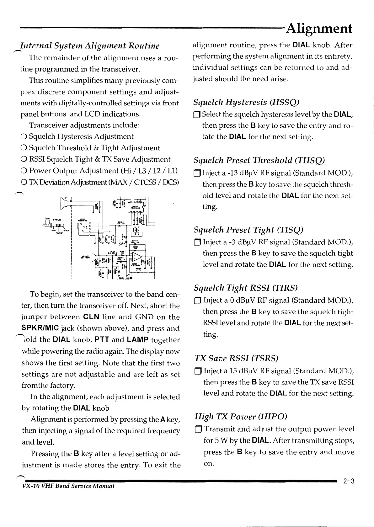
,!11~~:
~~KR
ctO
...
To begin, set
the
transceiver
to
the
band
cen-
ter,
then
turn
the
transceiver off. Next,
short
the
jumper
between
CLN
line
and
GND
on
the
SPKR/MIC jack
(shown
above),
and
press
and
-
told
the
DIAL
knob,
PTT
and
LAMP
together
while
powering
the radio again. The display
now
shows
the
first setting.
Note
that
the
first
two
settings
are
not
adjustable
and
are
left
as
set
fromthe factory.
In
the
alignment, each
adjustment
is selected
by
rotating
the
DIAL knob.
Alignment is performed
by
pressing the A key,
then
injecting a signal of the
required
frequency
and
level.
Pressing
the
B
key
after a level setting
or
ad-
justment
is
made
stores
the
entry.
To
exit
the
-
Alignment
alignment
routine,
press
the
DIAL knob.
After
performing
the
system
alignment
in
its entirety,
individual
settings
can
be
returned
to
and
ad-
justed
should
the
need
arise.
Squelch Hysteresis (IISSQ)
0 Select the squelch hysteresis level
by
the DIAL,
then
press the B
key
to save the en
try
and
ro-
tate the
DIAL for
the
next setting.
Squelch Preset Threshold (THSQ)
0 Inject a -13 dB)l V RF signal (Standard MOD.),
then press the
B key to save the squelch thresh-
old
level
and
rotate
the
DIAL for
the
next
set-
ting.
Squelch Preset
Tight
(TISQ)
0 Inject a -3
dB).lV
RF signal
(Standard
MOD.),
then
press
the B key to save
the
squelch
tight
level
and
rotate
the
DIAL for the next setting.
Squelch
Tight
RSSI
(TIRS)
0 Inject a 0
dB).lV
RF
signal
(Standard
MOD.),
then
press
the B key to save
the
squelch tight
RSSI
level
and
rotate the DIAL for the next set-
ting.
TX
Save
RSSI
(TSRS)
0 Inject a
15
dB).lV
RF signal
(Standard
MOD.),
then
press
the
B
key
to save
the
TX
save
RSSI
level
and
rotate the DIAL for
the
next setting.
High
TX
Power
(HIPO)
0
Transmit
and
adjust
the
output
power
level
for
5 W
by
the
DIAL. After
transmitting
stops,
press
the
B
key
to
save
the
entry
and
move
on.
----------------------------------------------------------
2-3
VX-10 VHF Band Service
Manual
 Loading...