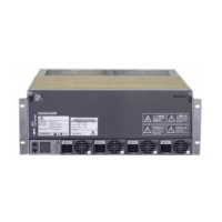
Chapter 2 Installation Instruction 9
NetSure 731 A41 Subrack Power System User Manual
is not selected, It can be used for dry contact. NetSure 731 A41-S1 provides four extended dry contacts: DO3、DO4、
DO5 and DO6,the illustration is as shown in the following:
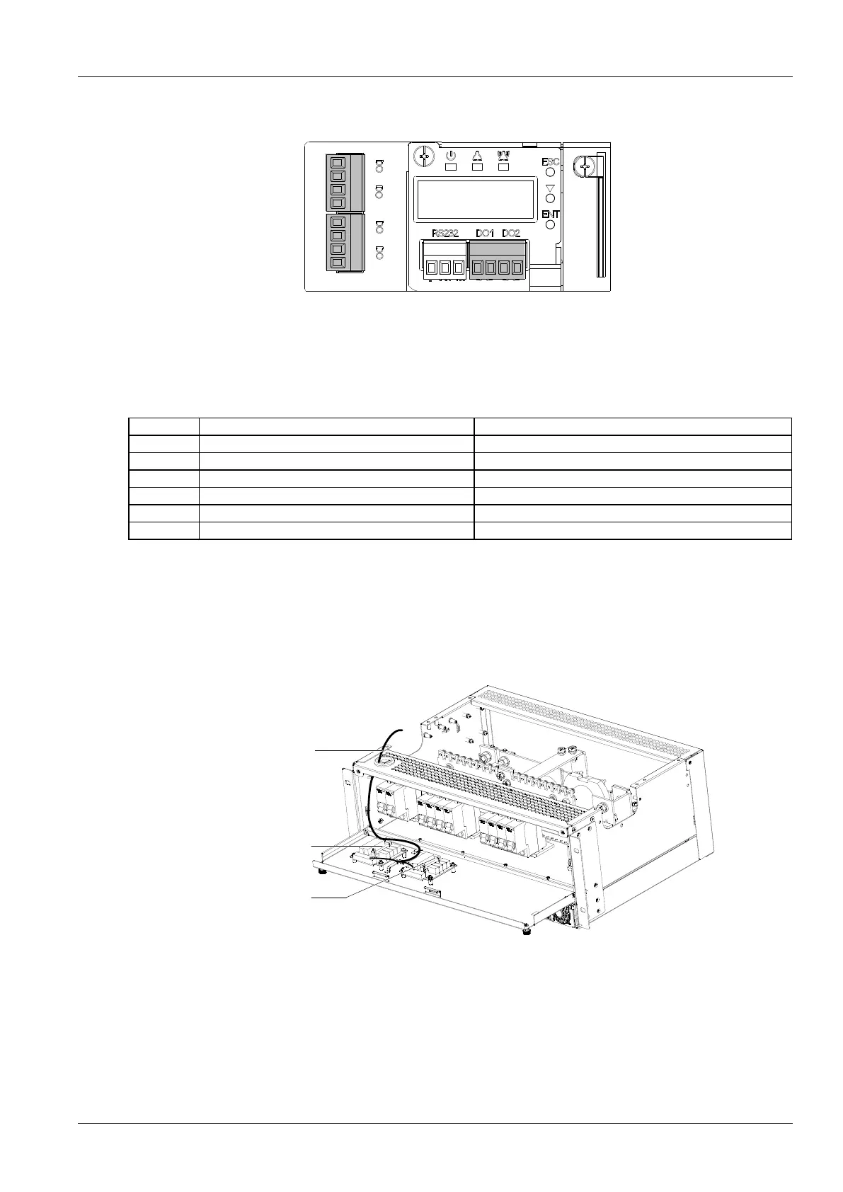
Figure 2-11 M225S1X1usr interface board illustration
Digital output dry contact specification of M225S controller and M225S1X1user interface board is as following:
Digital output:relay isolation,max:30Vdc 1A,125Vac 0.5A,60W;Min:10uA@10Vdc.
The dry contacts definition of M225S controller and M225S1X1 user interface board is shown in Table 2-5.
Table 2-5 Dry contact definition
Load disconnection control
LLVD control, user can't use it when LLVD is selected.
DC overvoltage or DC undervoltage
Except rectifier lost and multi-rectifier alarm.
Battery protection and load disconnection alarm.
In the controller normal state, the alarm contacts are always open, when system issues above alarms, related
contacts will be closed. All the status changes should be verified by a multimeter. After the alarms are removed, the
dry contacts (DO) should back to the open state.
Connecting NetSure 731 A41-S2 Signal Cables
W2453X1 user interface board provides dry contacts for NetSure 731 A41-S2.W2453X1 user interface board position
and signal cabling as shown in Figure 2-12.
Signal cable
User interface board
User interface board
(Flexible configuration)
Figure 2-12 NetSure 731 A41-S2 user interface board illustration
At most two W2453X1 user interface boards are allowed in the power system. Standard cabinet is only configured
with one user interface board.
With one W2453X1 user interface board configured, the power system provides four external digital input ports: DI1,
DI2,DI3,DI4 and four dry contact alarm output ports
With two user interface boards configured, the power system provides additional four dry contact alarm output
interfaces: DO5,DO6,DO7,DO8.
 Loading...