12 Chapter 2 Installation Instruction
NetSure 731 A41 Subrack Power System User Manual
Name of double-layer port
Common contact of relay 2
Common contact of relay 3
Common contact of relay 4
Common contact of relay 5
Common contact of relay 6
Common contact of relay 7
Common contact of relay 8
The definition of dry contact function can be set through controller or the WEB browser.
The specifications of the dry contact ports are as follows:
Digital inputs: 8-route, opto-isolation, the alarm and high/low level are definable (high level: 20V ~ 60V, low level: less
than 1V).
Digital output: 8-route, relay isolation, maximum: 30Vdc 1A, 125Vac 0.5A; 60W; minimum: 10uA @ 10Vdc, alarm is
definable.
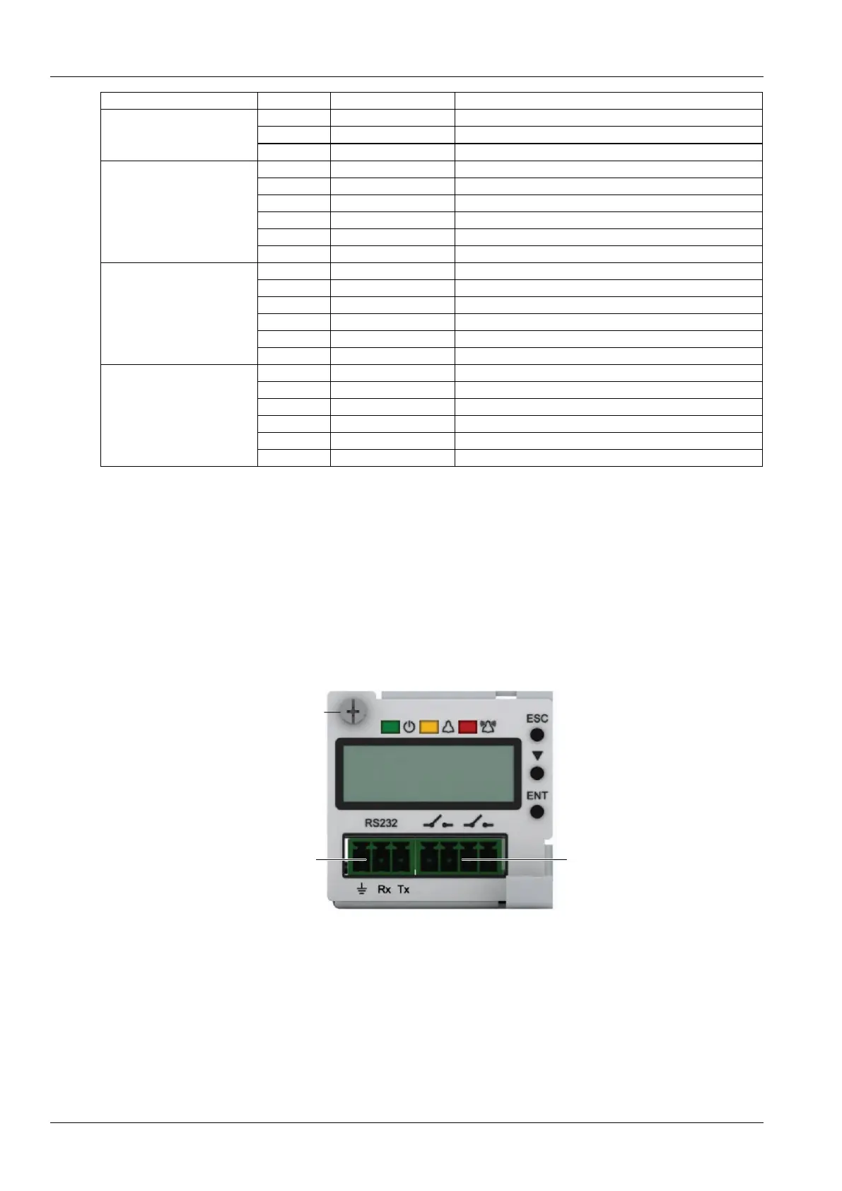
Connecting Communication Signal Cable
The RS232 communication port of M225S controller is shown in Figure 2-14.
RS232 communication
serial port
Dry contact output
Figure 2-14 M225S controller communication port
The communication port of the M221S controller is shown in Figure 2-15.M222S only provides the RS232
communication serial port, whereas the Ethernet port is not provided.
 Loading...