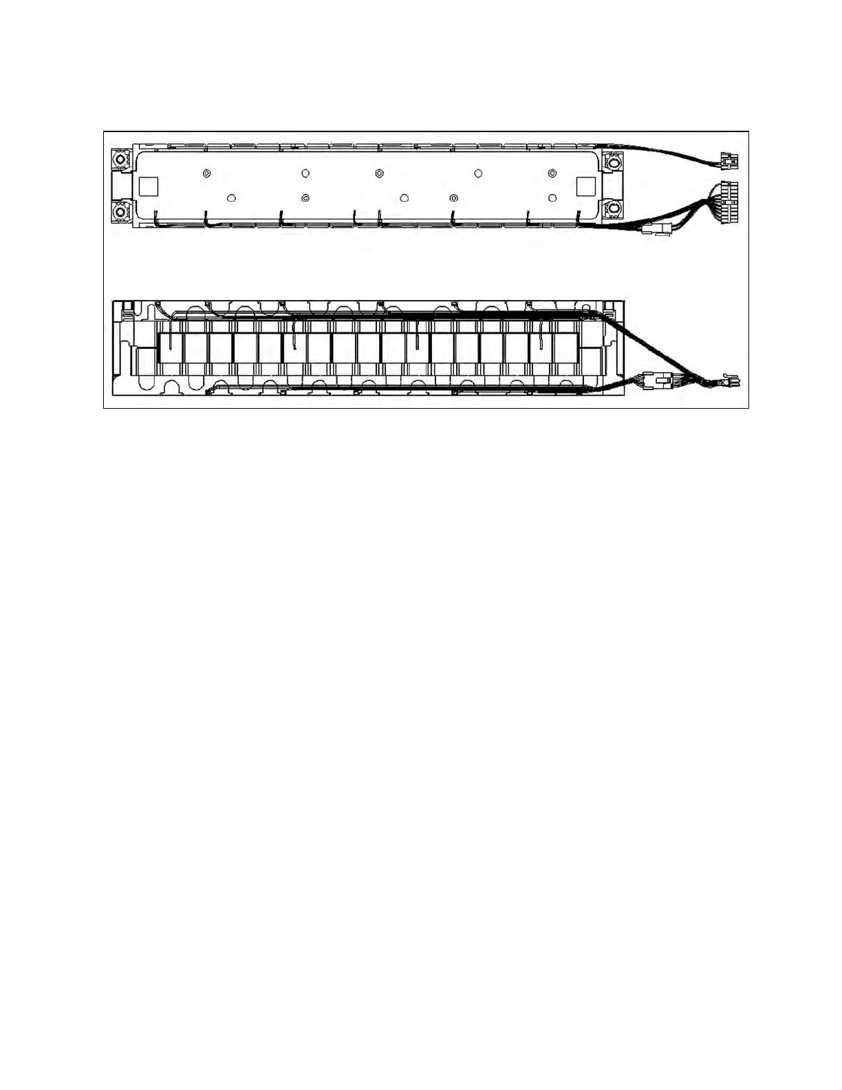
Figure 2.5 Structure Diagram of Vertiv™ Liebert® APM2 Lithium Battery Module
2.5.2 Electrical control components
The key components of the electrical control of the Liebert® APM2 lithium battery module are specified as below:
• MCB: It is the MCB of the low voltage battery power supply system with the breaking capacity of 6 A, 440 VDC. It
is used as the switch to supply power to the low voltage system of the lithium battery module. When the battery
needs to be powered on after being placed into the cabinet, close the MCB first to keep the low voltage system
powered on.
• Main contactor: For lithium module ON and OFF active control.
• Fuse: Passive protection device, the fuse supports the lithium battery module when the external short circuit
occurs fast fuse, to protect the main circuit battery or device, to prevent dangerous events.
• Lock switch: Used for lithium battery module into the cabinet detection, control of the main circuit contactor
unilateral control and system contactor disconnection and lithium module cold start applications.
.
10 Proprietary and Confidential ©2024 Vertiv Group Corp. 2 Overview
Vertiv™ Liebert® APM2 Lithium Battery Module Installer/User Guide

 Loading...