REV : 0
REV DATE : 1/19
DPN004899
Page :1 /1
Form No.: DPN001040_REV4
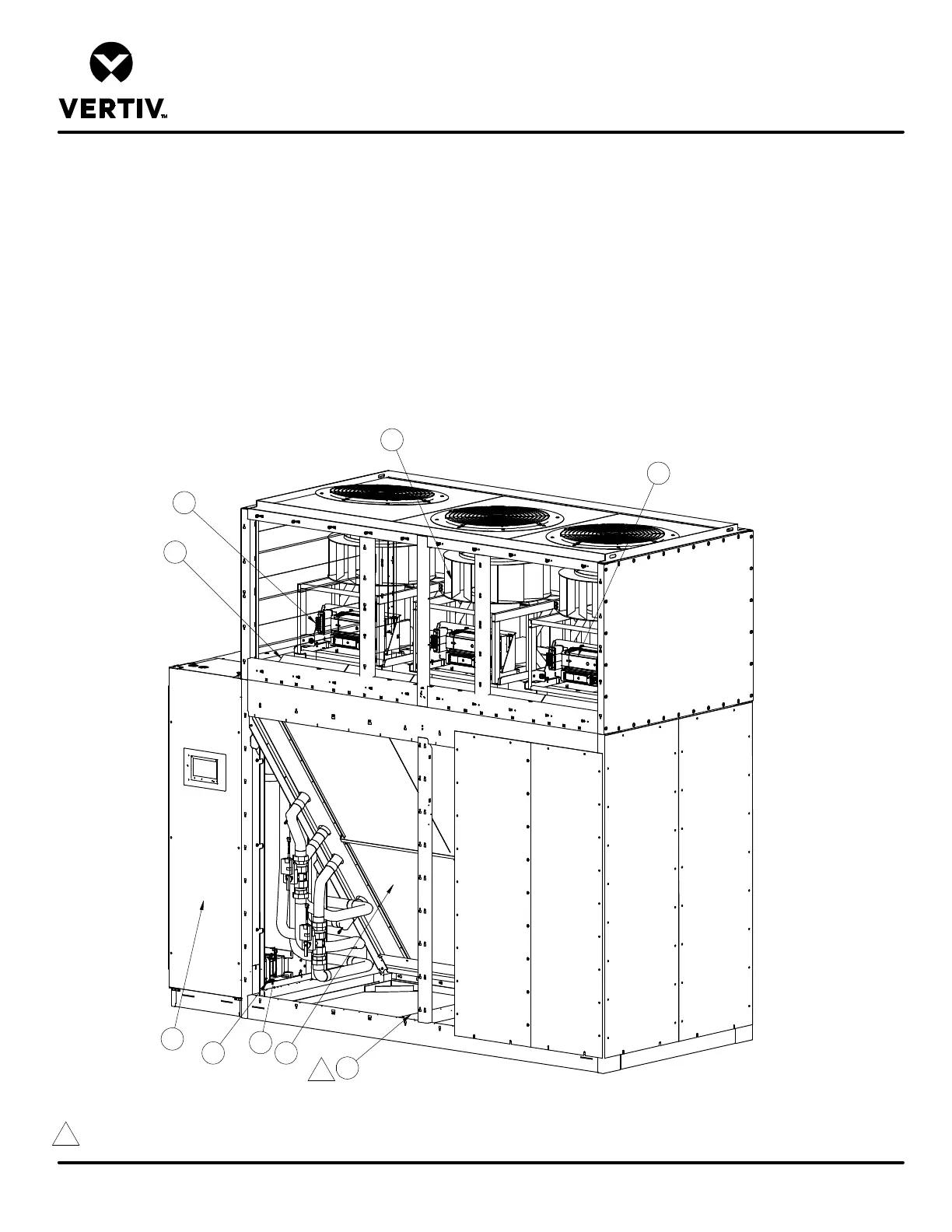
LIEBERT CW
CW305, 375, 415 W/ BOTTOM DISCHARGE
COMPONENT LOCATION DIAGRAM
1. Blower/Motor (Typical 3)
2. Line Reactor Transformers (Typical 3)
3. Evaporator Coil
4. Air Filters
5. Condensate Pump (optional, shipped loose)
6. Electric Panel
7. THD Mitigation Device (optional)
8. VFD Assemblies (Typical 3)
9. 575V Transformer (if applicable)
Notes:
1. Electrical Compartment (item #6) shown on left side of unit. Unit may be ordered with Electrical Compartment on either side, or with Electrical Compartment facing into Gallery space.
2. Condensate Pump (if ordered) to be shipped loose and attached to this frame member for shipping. Customer to locate and install.
6
3
Panels removed
for clarity
4
8
1
2
9
5
2
7