Rear
Rear
Rear
Li
st 20, 25
List 27
List 21, 26
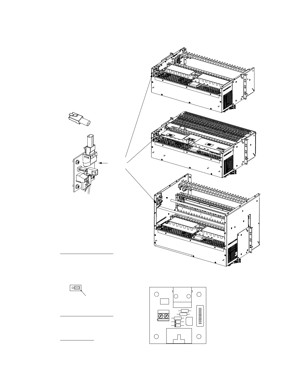
System
Interface
Board
J2 Controller
CAN Port (RJ-45)
A CAN termination plug
(P/N 548398) must be
installed if an external
device or system is not
connected here.
System Interface Board P/N 555484
J3 on System Interface Board
Wire Size Capacity: 16 AWG to 30 AWG.
Wire Strip Length: 0.32 inch.
Recommended Torque: 2.3 in-lbs.
RS485 Connection
J3-1: RS485+
J3-2: RS485-
J1
J2
J3
J4
J5
1
1
555484
0 0 0 X X X X X
A X X X X X X X X
1
No
Battery
Pwr
Battery
Pwr
Shorting
Jumper
J4 on System Interface Board
Selects to power controller
from “Battery Power” or not
if a battery LVD contactor is furnished.

 Loading...


