Chapter 2 Installation Instruction 5
NetSure 731 A91 Subrack Power System User Manual
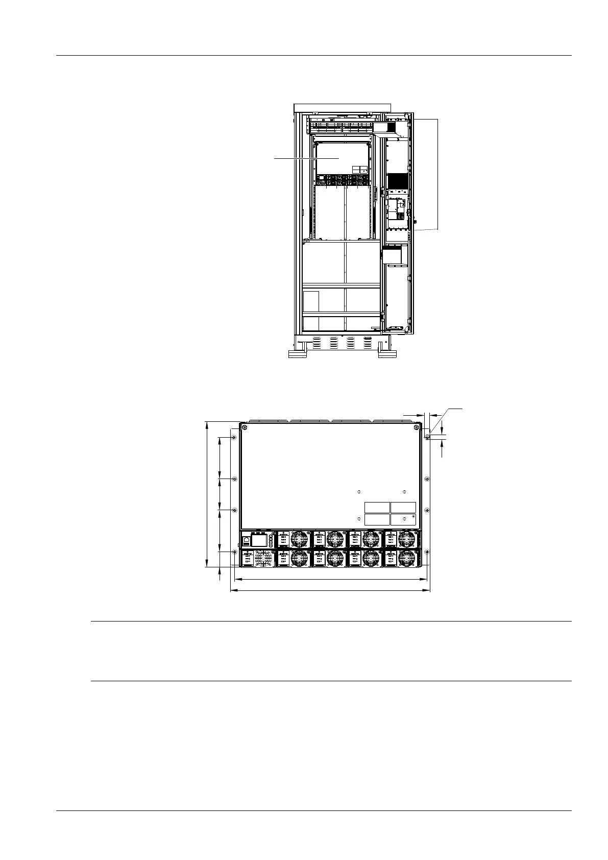
Installed in cabinet
Insert the subrack power system to the matching cabinet, as shown in Figure 2-2.
Figure 2-2 Installed in the cabinet system
The engineering graphics of the subrack power system as shown in Figure 2-3.
Figure 2-3 Installation size of 731 A91-S1/S2/S3
(
unit:
:
mm
)
Note
1. Tighten the captive screw of the MFU Panel by the cross head screwdriver when there is no operation.
2. Also tighten the handle by the cross head screwdriver.
3. Please plug in the new modules or installing a new panel after removing the rectifier module.
2.4 Electrical Installation
2.4.1 Power System Cabling Method
Cabling from the top of the power system
The top cover is rubber ring top cover.

 Loading...


