EasyManua.ls Logo

Vertiv NetSure 731 A91 - Chapter 1 Overview; System Composition and Configuration; Power System Composition; Power System Configuration

Vertiv NetSure 731 A91
40 pages
To Next Page IconTo Next Page
To Previous Page IconTo Previous Page
Loading...
Chapter 1 Overview 1
NetSure 731 A91 Subrack Power System User Manual
Chapter 1 Overview
This chapter introduces model composition and configuration and features of NetSure 731 A91-S1, NetSure 731
A91-S2 and NerSure 731 A91-S3 (abbreviated as 'power system' hereinafter).
1.1 Composition and Configuration
Composition
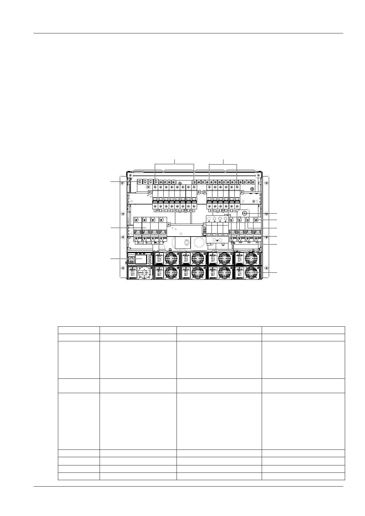
The power system is composed of power distributionrectifier modules and controller module.
Take NetSure731 A91-S1 for example, the internal structure is shown as Figure 1-1.
Earthing screw
AC input terminal N
AC input terminal L3
AC input terminal L2
AC input terminal L1
Positive terminal
Battery MCB
Controller
Rectifier
Non- prority load
Prority load
Figure 1-1 NetSure 731 A91- S1 system instruction
Configuration
The configuration of the power system is listed in Table 1-1.
Table 1-1 Configuration of power system
Item
NetSure 731 A91-S1
NetSure 731 A91-S2
Controller
Mode: M830B
Mode: M530B
Rectifier
Model:
R48-3500e3
Maximum configuration
9 pieces
Model
R48-3000e3/R48-3500e3
Maximum configuration
9 pieces
Note: R48-3000e3 moudle and
R48-3500e3 moudle are not mixed
AC power
distribution
3P
N
PE/380-415Vac
3P
N
PE/380-415Vac
DC power
distribution
PL:
63A/1P×2 MCB
32A/1P×2 MCB
16A/1P×2 MCB
NPL:
63A/1P×3 MCB
32A/1P×3 MCB
16A/1P×2 MCB
PL:
63A/1P×2 MCB
32A/1P×2 MCB
16A/1P×2 MCB
NPL:
63A/1P×3 MCB
32A/1P×3 MCB
16A/1P×2 MCB
AC output MCB
/
/
Battery MCB
4
×
125A/1P
4
×
125A/1P
AC SPD
1 piece
1 piece
DC SPD
1 piece
1 piece

Related product manuals