Chapter 2 Installation Instruction 9
NetSure 731 A91 Subrack Power System User Manual
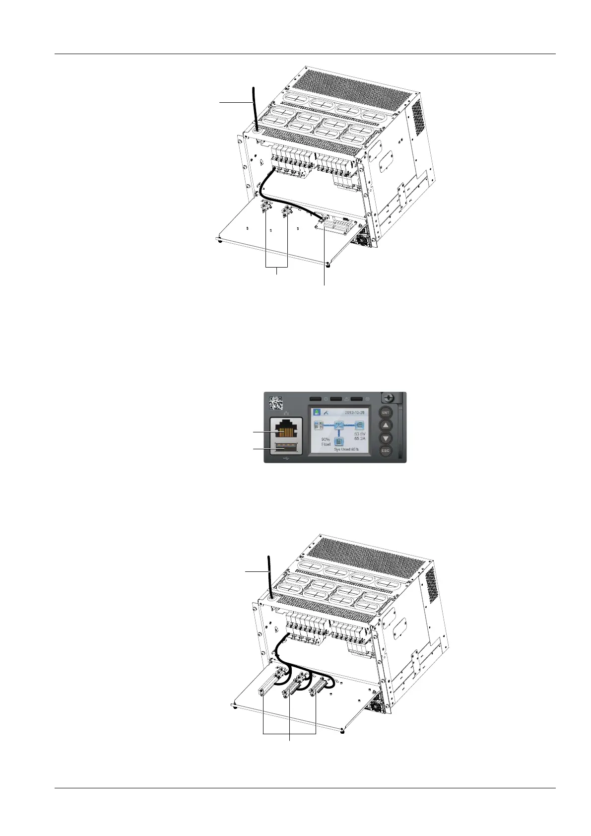
Terminal block
User interface board
(DI/ DO board)
Signal cable
Figure 2-9 Netsure 731 A91-S1 user interface board illustration
MA4C5U31 User Interface Board can provide 8 DI and 8 DO. For alarm type and corresponding relay, users can set
it by background software according to the actual situation.
Connecting Communication Signal Cable
The communication port of M830B controller is shown in Figure 2-10.
Figure 2-10 M830B controller communication port
Connecting NetSure 731 A91-S2 Signal Cables
The standard configuration of the system is M530B controller. Netsure 731 A91-S2 user interface board position as
shown in Figure 2-11.
Signal cable
User interface terminal
(DI/ DO board)
Figure 2-11 Netsure 731 A91-S2 user interface board illustration

 Loading...


