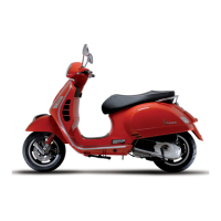
Do you have a question about the Vespa PK 125 and is the answer not in the manual?
Defines the Vespa models covered by this service manual amendment.
Describes the pressed sheet, monocoque structure of the chassis.
Details the steering pivot and suspension types.
Lists key specifications for PK 50, PK 50S, and PK 50S Elestart models.
Explains frame and engine serial number prefixes.
Lists key specifications for PK 125 and PK 125S models.
Details engine checks at 1000km, 4000km, 8000km, and overhaul.
Details gear box checks at 1000km, 4000km, 8000km, and overhaul.
Instructions for dismantling and cleaning the air filter.
Instructions for checking and adjusting the spark plug electrode gap.
Instructions for decoking the exhaust pipe.
Covers maintenance of bearings, speedometer drive system, and gear selector.
Details adjustment procedures for Bowden control cables.
Refers to the locking torque table for critical fasteners.
Lists specific lubricant types and brands for various components.
Wiring diagrams for 6V, 4-pole flywheel systems, basic and without horn.
Wiring diagrams for mixed voltage, 4-pole systems with turn signals/stop lights.
Wiring diagrams for 6V, 6-pole flywheel systems, basic and with stop/tell-tale.
Wiring diagrams for 12V, 6-pole flywheel systems with various features.
Wiring diagrams for 12V, 6-pole systems with electric starting and other features.
Highlights the benefits of electronic ignition over traditional systems.
Details the electrical benefits like consistent spark and longer plug life.
Details the mechanical benefits like reduced maintenance and reliability.
Describes the main component parts of the 4-pole flywheel ignition system.
Describes the main component parts of the 6-pole flywheel ignition system.
General precautions to prevent damage when working on electrical circuits.
Steps for diagnosing and troubleshooting ignition system problems.
Procedures for checking and adjusting engine ignition timing.
Compares Elestart ignition components to standard 6-pole systems.
Procedure for testing the low tension section of the flywheel magneto.
Procedure for testing the voltage regulator's performance.
Details battery type, specifications, and initial service procedures.
Covers checking electrolyte level, charge condition, and charging methods.
Lists the main features and specifications of the electric starter motor.
Details no-load, under-load, and start test procedures for the starter motor.
Step-by-step instructions for dismantling the starter motor.
Procedures for replacing parts like pinion, brushes, and armature.
Details tools for lubricating transmission cables.
Details tools for steering column overhaul and ring nut adjustment.
Details tools for securing flywheel magneto.
Details punches for roller cages.
Details the tool for caulking the protection cap.
Procedure for removing the flywheel rotor using specific wrenches.
Procedure for removing the steering column upper ring nut.
Steps for disassembling the front wheel brake drum and jaw holder disc.
Steps for disassembling brake drum bearings and oil seals.
Describes factory markings on pistons and cylinders for correct matching.
Provides tables with dimensions and clearances for piston/cylinder fitting.
Explains how to match connecting rods and roller cages by category.
Specifies the maximum admissible clearance for the wrist pin after use.
Specifies the maximum admissible axial clearance for the connecting rod.
Procedures for dismantling tab washers and pin/roller bushes.
Instructions for assembling the pin into the steering column assembly.
Instructions for assembling oil seals and roller bushes with tab washers.
Step-by-step instructions for drilling and removing the lock cylinder.
Instructions for reassembling the lock cylinder and checking operation.
Guidance for fitting security locks to cowl flaps, saddle, and glove compartment.
Explains the 19.1.20018 tool for lubricating transmission cables.
Details controlling and fitting the transmission cable end cap.
Instructions for the final lubrication step using spray liquid.
Steps for dismantling, washing, and drying the carburettor components.
Table of specifications for different carburettor models and jets.
Tests for headlamp bulb voltage under various flywheel magneto conditions.
Lists the required instruments for testing the voltage regulator.
Step-by-step instructions for testing the voltage regulator with a vehicle.
Guidance on interpreting test results to determine regulator efficiency.
Specifies torque values for engine unit fasteners.
Specifies torque values for front suspension fasteners.
Specifies torque values for steering unit fasteners.
Specifies torque values for wheel unit fasteners.
Instructions for assembling the drive shaft using specific tools.
Procedure for checking engine timing with a 4-pole flywheel magneto.
Procedure for checking engine timing with a 6-pole flywheel magneto.
Details assembly steps for brake drum components like roller cages and bearings.
Details installation steps for the jaw anchor plate and circlip on the front axle.
Details the procedure for locking the front wheel drum, including torque.
Advises on test preparation, auxiliary tank, and environmental conditions.
Instructions for performing the test, including rider weight and speed.
Provides acceptable fuel consumption figures for various Vespa models.
Checklist of operations after overhauling the engine or vehicle units.
Instructions for cleaning the vehicle exterior, engine, and painted parts.
Instructions for correctly setting the headlamp alignment.
Ensures correct battery polarity connections to prevent regulator damage.
Advice for dealers to perform checks on new vehicles before consignment.
| Transmission | 4-speed manual |
|---|---|
| Brakes (Front) | Drum |
| Brakes (Rear) | Drum |
| Fuel System | Carburetor |
| Cooling System | Air cooled |
| Engine Type | Single-cylinder, 2-stroke |

