2
CONGRATULATIONS
!
The lightning flash with arrowhead symbol,within an equilateral triangle,is intended to
alert theuser to the presence of uninsulateddangerous voltagewithinthe product's
enclosurethatmaybeofsufficientmagnitudetoconsituteariskofelectricshocktopersons.
Theexclamationpointwithinanequilateraltriangleisintendedtoalerttheusertothepresence
ofimportantoperatingandmaintenance(servicing)instructionsintheliteratureaccompanying
theappliance.
T0 REDUCE THE RISK 0F FIRE 0R ELECTRlC SHOCK,DO NOT
EXPOSETHISAPPLIANCET0 RAIN0RM0ISTURE.
CAUTl0N:TOREDUCETHERlSKOFELECTRlCSHOCK
DONOTREMOVECOVER(ORBACK)
NOUSER-SERVICEABLEPARTSINSIDE
REFERSERVlCINGT0QUALIFIEDSERVlCEPERSONNEL
CAUTION
RISKOFELECTRICSHOCKDONOTOPEN
CONTENTS
CAUTION⋯⋯⋯⋯⋯⋯⋯⋯⋯⋯⋯⋯⋯⋯⋯⋯⋯⋯⋯
2
IMPORTANT SAFEGUARDS
⋯⋯⋯⋯⋯⋯⋯⋯⋯⋯⋯⋯⋯⋯⋯⋯⋯⋯⋯
3
FEATURES⋯⋯⋯⋯⋯⋯⋯⋯⋯⋯⋯⋯⋯⋯⋯⋯⋯⋯⋯
4
CONTROLS AND FUNCTIONS
⋯⋯⋯⋯⋯⋯⋯⋯⋯⋯⋯⋯⋯⋯⋯⋯⋯⋯⋯
5
TOP PANEL ⋯⋯⋯⋯⋯⋯⋯⋯⋯⋯⋯⋯⋯⋯⋯⋯⋯⋯⋯⋯ 5
FRONT PANEL ⋯⋯⋯⋯⋯⋯⋯⋯⋯⋯⋯⋯⋯⋯⋯⋯⋯⋯⋯⋯ 6
REAR PANEL ⋯⋯⋯⋯⋯⋯⋯⋯⋯⋯⋯⋯⋯⋯⋯⋯⋯⋯⋯⋯ 6
HOW TOCHANGE THE FADER UNIT
⋯⋯⋯⋯⋯⋯⋯⋯⋯⋯⋯⋯⋯⋯⋯⋯⋯⋯⋯⋯ 7
CONNECTION DIAGRAM
⋯⋯⋯⋯⋯⋯⋯⋯⋯⋯⋯⋯⋯⋯⋯⋯⋯⋯⋯⋯ 8
SPECIFICATIONS ⋯⋯⋯⋯⋯⋯⋯⋯⋯⋯⋯⋯⋯⋯⋯⋯⋯⋯⋯⋯ 8
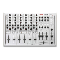
ThankyouforpurchasingtheVestaxVMC-002MixingController.Wesuggestthatyou
readthroughthisowner'smanualthoroughlysothatyoumayenjoythefulluseofthis
productsafetyandintheknowledgeofallitsspecialfeaturesandsuitablyapplications.