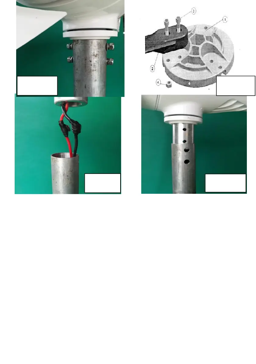
3) wind blades is mounted on the flange,pay attention to the word with a
face outward (as shown in Figure 6), with M6*20 (3) Hexagon screw and
M6 self-locking nut will be connected to the flange,self-locking nut fixed in
the flange groove with a 5mm hex wrench locking tightly (shown in Figure
7), in this way, the other two wind blades fixed on the flange, adjust the
distance between the two tips within 5.0mm and then tighten the bolts to
ensure that the wind turbine balance (as shown in Figure 8)