OSSC Quick Start Guide VideoGamePerfection.com
Power input – Connect a suitable 5 volt, 2.1 x 5.5mm positive tip PSU supplying at least 1 amp of
current.
The OSSC has been designed as a next-generation line-doubler. Rather than a fully blown video
processor, the OSSC is designed to process individual scanlines in real time. Because of this, the
unit can convert between the 15khz video that your retro consoles output and the 31khz video that
modern displays work best with, with only a few microseconds of input lag.
Connecting your OSSC
Connect a suitable power supply (5 volts, 1 amp postive tip) to the
OSSCs power connector. Connect a DVI or HDMI cable between the
video out on the OSSC and your display. Almost any display that
supports HDMI or DVI-D can be used, but please remember OSSC does
not adhere fully to DVI/HDMI specifications so compatibility cannot be
guaranteed. For displays that only have analogue inputs, a converter is
required. OSSC does not use HDCP, so any basic converter should work.
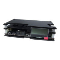
Ensure the PSU is turned on at the wall, then power on your OSSC using the power switch, the
LCD on the front of the unit should light up and display the current firmware version, as shown in
the picture. A letter ‘a’ after the firmware version number indicates audio capable firmware. Switch
your display to the correct input. If everything is working correctly, a grey test card pattern should
appear.
Connecting a console, PCB or other hardware
Power your OSSC off and connect a suitable source to the AV1, AV2 or AV3 connectors. For most
systems, using a properly wired RGB SCART cable connected to the AV1 input is the best option.
You can connect either 15khz or 31khz sources to any input on the OSSC, but remember that the
AV3 (VGA or D-Sub15) connector does not have the additional filtering that RGB SCART sources
often require.
Once you have connected your hardware, power on the OSSC. Select the appropriate input using
the remote or by pressing BTN0 until the LCD displays the correct input. Now, power on your
console, PCB or vintage computer hardware. You should now see it displayed on your TV or
monitor.
Options
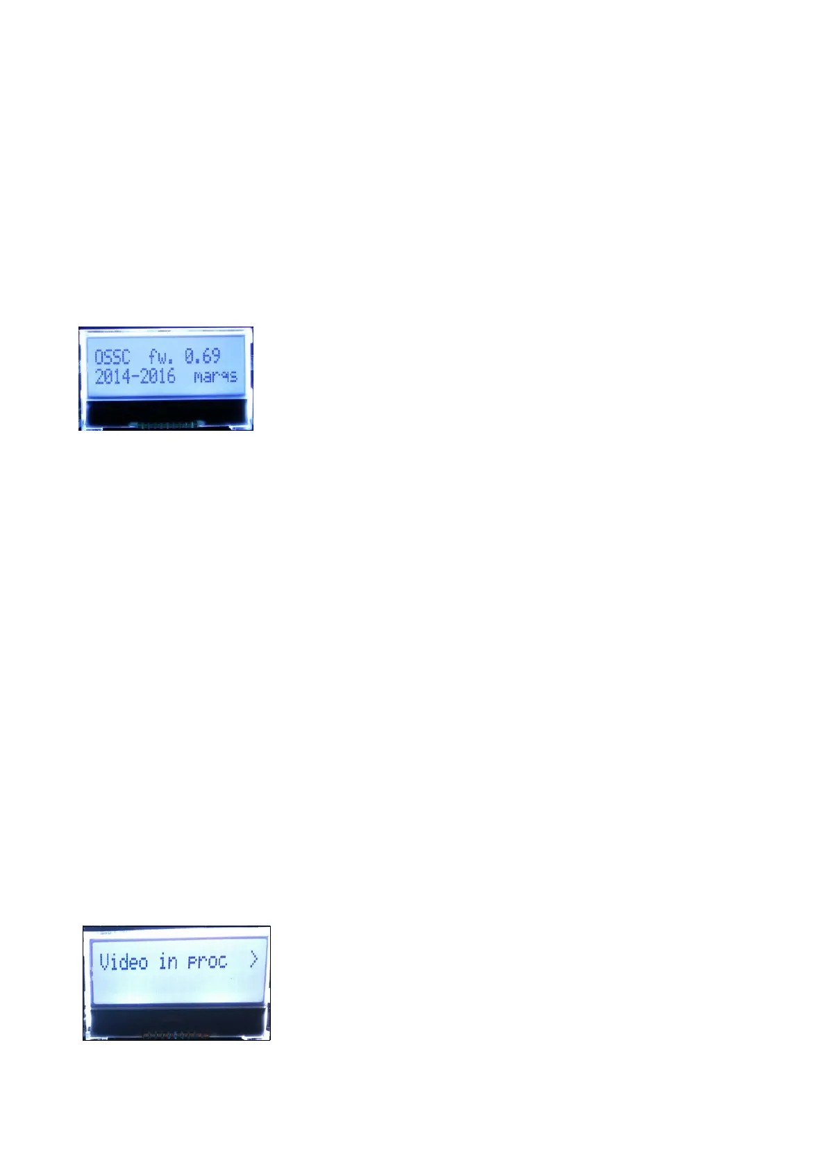
To access the OSSCs options menu, press the Menu on/off button on
the remote. The LCD on the front of the unit will then change to menu
mode, as shown in the picture on the left.
In the newer firmwares, options are now organised into sub-
categories. You can navigate between categories using the Prev/next
option buttons on the remote and select an option using OK button.
Page 6