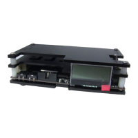
Buttons, connectors and external controls
In the overview pictures you can see the following features on your OSSC.
Status LEDs – Green LED indicates that power is on. This green LED will go out briefly when an
IR remote code is detected. The red LED indicates unstable sync when lit.
LCD – Displays the OSSCs menus and information about the current source.
MicroSD Card Slot – For updating the devices firmware, see “Firmware Updates”.
IR Sensor – Receives commands from the remote control unit. Line of sight is required.
JTAG Connector – For software development purposes and firmware updates.
BTN0 and BTN1 – Perform various functions without the need of a remote.
Video out – On 1.5 and earlier models, an industry standard DVI-D connector outputs digital video
at chosen resolution to your display. Does not support/output analogue DVI. On 1.6 models this is
replaced by a HDMI connector.
Audio out (V1.5 and earlier revisions only) – Standard 3.5mm stereo headphone plug type
connector. Audio fed in through AV1 (RGB SCART) will be output here. If an audio upgrade board
is installed, you can also feed in analogue audio through this connection, but please note if you do
you should disconnect the SCART cable from AV1.
AV2 audio in/AV1 audio out (V1.6 and later revision units only) - Standard 3.5mm stereo
headphone plug type connector. Use this connector to output audio from AV1/SCART or to input
audio for AV2/Component video sources.
Audio toggle (V1.6 and later revision units only) – Toggle between outputting audio from AV1 or
inputting and digitising audio on AV2.
AV3 audio in (V1.6 and later revision units only) - Standard 3.5mm stereo headphone plug type
connector. Use this connector to input and digitise audio for AV3/D-Sub15 (VGA) sources.
AV1 In – Connect an RGB SCART source to this input. Note the input must be RGB or Ypbpr, S-
video and composite SCART sources are not supported and require transcoding into RGB first.
Only European spec RGB SCART cables are supported, the less common Japanese JP21 cables
must be used with a converter, a suitable one can be purchased here -
https://www.retrogamingcables.co.uk/micomsoft-xrgb/european-scart-to-japanese-scart-converter
AV2 In – Connect component video or RGB with sync on green sources to this input.
AV3 In – Standard D-Sub15 (VGA) connector. You can connect sources such as the Sega
Dreamcast or a retro gaming PC. This input does NOT have a sync low pass filter as this is
normally not required for VGA connections.
Signals up to a maximum resolution of 720p are supported on all inputs.
Power Switch – Toggles power off and on.