77
77
7
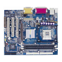
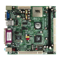
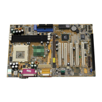
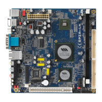
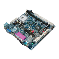
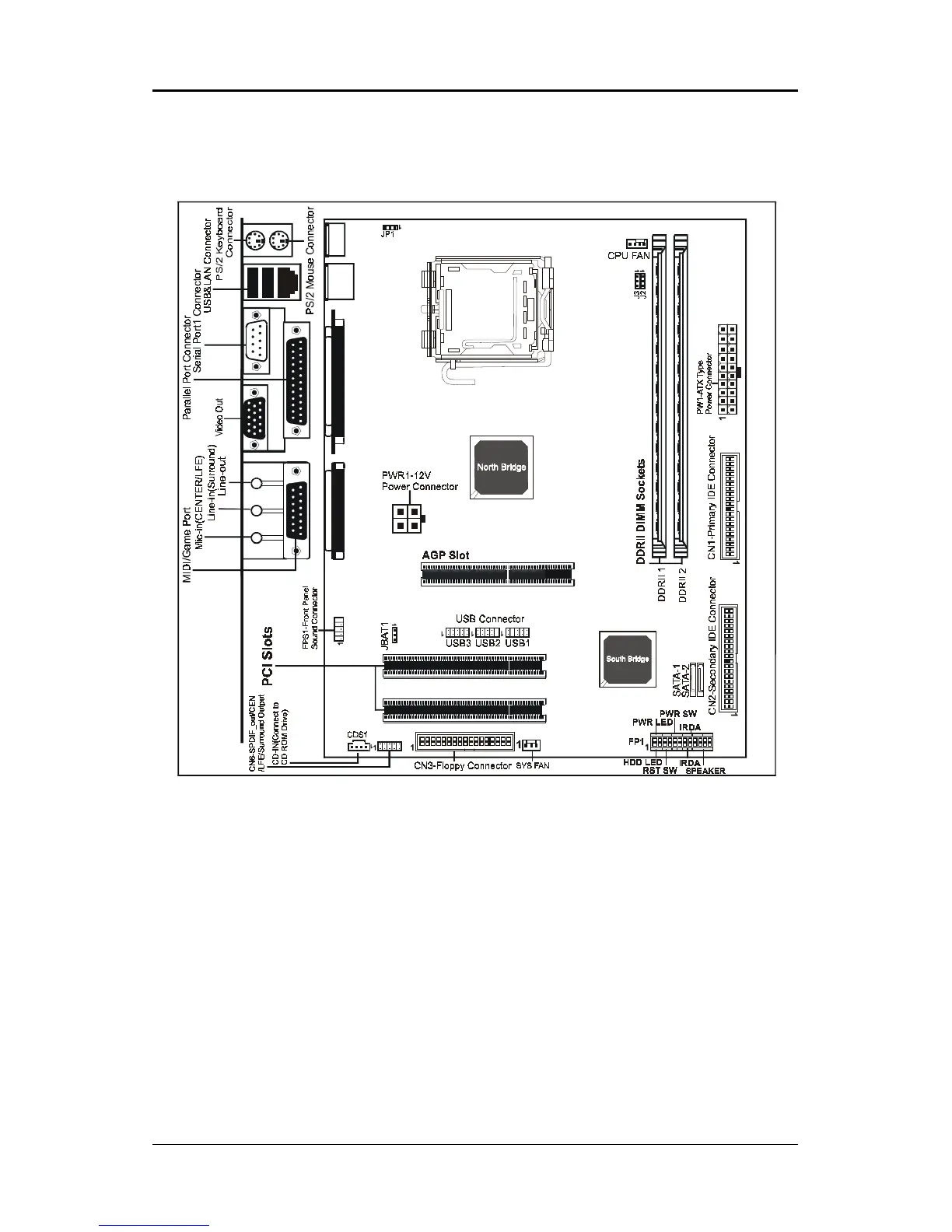
Motherboard LayoutMotherboard Layout
Motherboard LayoutMotherboard Layout
Motherboard Layout
The following diagram shows the relative positions of the jumpers, connectors, major
components and memory banks on the motherboard.
NOTE
1) Be sure to check the cable orientation in order to match the colored strip to the pin 1 end of the
connector.
2) Be sure to connect PW1 and PWR1 to power supply correctly, otherwise, the motherboard can’t
work normally.
3) When you start up the system, please wait for 5 seconds after you power on AC.
4) Adding a metal spaced plate to the back of the Socket 775 is not recommended as
this will short motherboard components and damage the system.
FOXCONN
REMOVE
LGA775 Socket