Do you have a question about the VIAIR 10005 and is the answer not in the manual?
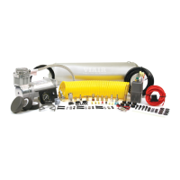
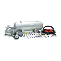
Lists components for air tank installation, including bolts, washers, bushings, drain cock, safety valve, and fittings.
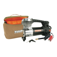
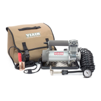
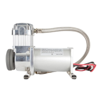
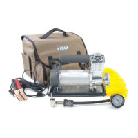
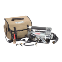
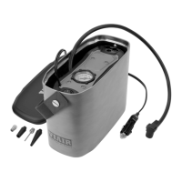
Lists components for compressor installation, including mounting hardware, air filters, fuse holder, wire, and clips.
Details the pressure switch with relay and the NPT reducer fitting included in the kit.
Lists components for dash panel gauge installation, including gauge, mounting hardware, terminals, and connectors.
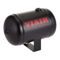
Instructions for installing compression and quick connect fittings onto the air tank ports, emphasizing thread sealant.
Guidance on using rubber bushings and bolts to securely mount the air tank to the vehicle chassis.
Critical safety information including pressure limits, breathing device prohibition, and servicing precautions.
Essential safety warnings regarding electrical shock, disassembly, water exposure, and unattended use.
Guidelines for choosing a flat, secure, cool location close to the battery, away from water and flammable liquids.
Step-by-step instructions for connecting the compressor's power and ground wires to the vehicle's electrical system.
Information on duty cycle, thermal overload protector, and recommended engine operation during use.
Routine checks for connections, screws, filter elements, and general cleaning; emphasizes authorized repairs.
Advice on remote intake filter use, noise reduction, mounting height relative to tank, and marking mounting holes.
Guidance on proper pressure switch mounting for accurate readings and avoiding over-pressure ratings.
Notes on factory-tested gauge calibration, avoiding adjustment of compression fittings, and pressure limits.
Combines location, air lines, routing, firewall precautions for installation.
Step-by-step guide for connecting the dash panel gauge's ON/OFF switch to the pressure switch and power.
Instructions for connecting the gauge's illumination wires to a fused circuit and ground source.
Final mounting steps for the gauge, securing wiring and air lines with zip ties to prevent interference.
Guide on connecting the gauge's power wire to the vehicle's power source after ensuring the switch is OFF.
Procedure for running the compressor, checking for leaks, and verifying system operation after installation.
Addresses tank pressure drops when the compressor shuts off, citing loose fittings, check valves, or drain cocks.
Covers compressor running continuously with low airflow or safety valve activation due to air usage or leaks.
Identifies causes for the compressor not starting, such as no power, blown fuse, overheating, or faulty pressure switch.
Addresses thermal overload protector cut-outs from poor ventilation and excessive knocking/rattling from loose parts.
Explains compressor duty cycle as the ratio of on-time to total cycle time at specific PSI and temperature.
Emphasizes operating compressors within their rated working pressure and selecting pressure switches accordingly.
A chart correlating amp draw, wire length, and recommended wire gauge for 12-volt systems.
A visual representation of the system's electrical connections, including battery, fuse, compressor, and dash panel.
Details the one-year warranty against defects in workmanship and materials, and how to obtain service.
Disclaimer regarding manual ownership, reproduction rights, and VIAIR's liability for its content.
| Model | 10005 |
|---|---|
| Max Pressure | 150 PSI |
| Voltage | 12V |
| Inlet Port Size | 1/4" NPT |
| Duty Cycle | 100% |