MOUNTING AND WIRING
1. Disconnectgroundcablefromvehicle’sbattery.
2. Temporarily position the air compressor in the location where it will be mounted.
3. Routegroundwiretothenegativepostofthebatteryortoanappropriategroundingpointand
cut ground wire to length as needed.
4. Mountaircompressorwiththefoursetsof13/64”(5mm)bolts,nuts,washers,andlocking
washersprovided.(SeeFig.2forMountingInstructions)Useofthreadsealantisrecommended.
5. NOTE:ForRemoteInletAirFilterInstallation,refertoRemoteInletAirFilterInstallation
InstructionincludedintheRemoteInletAirFilterPackforinstallationofRemoteInletAirFilter.
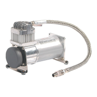
6. Thisaircompressorcomeswith1.5ft.heavydutyheatresistantleaderhosewith_”ttings.
Thisleaderhoseisdesignedtoprolongthelifeofyourairline.Donotremovethisleaderhose
from air compressor.
7. IMPORTANT:Pleasenote,theleaderhosethatcomeswithyourcompressormayhaveabuilt-in
inlinecheckValve.DONOTremoveinlinecheckvalvefromleaderhose.
8. Selectproperlocationtomountleaderhosewithhosebracketprovided.Avoidlocationswhere
leader hose may become tangled with wires and other hoses.
9. Tomounthosebracket,drillholewith3/16”drillbitandpushself–anchoringhosebracketpin
intohole.Routeleaderhosethroughhosebracketandsecurehosebypressingbracketclamp
into locked position.
10.Toremovehosefromthehosebracket,simplypressdownonthehoseclampreleasetabto
release bracket clamp. (Fig. 3)
11.Connectcompressorpositiveleadwiretooneoftheleadsofyourpressureswitch.
12.Makesurethatyourcompressorsetupisproperlyfused.Forappropriatefusesize,referto
ampdrawofcompressorintheSpecicationssectionofthismanual.
13.Alwayslocatefuseascloseaspossibletopowersource.
14. Before connecting to power source, re-check to make sure that all connections are
properly connected.
15.Connectandtestcompressorsystembyrunningthecompressorforashorttimetobuildup
pressure in your air tank.
16. Once air pressure reaches preset cut out pressure of your pressure switch, the compressor
will shut off. Inspect all air line connections for leaks with soap and water solution.
Ifaleakisdetected,theairlinemaynotbecutsquarelyorpushedallthewayin.
Tighten connections if needed.
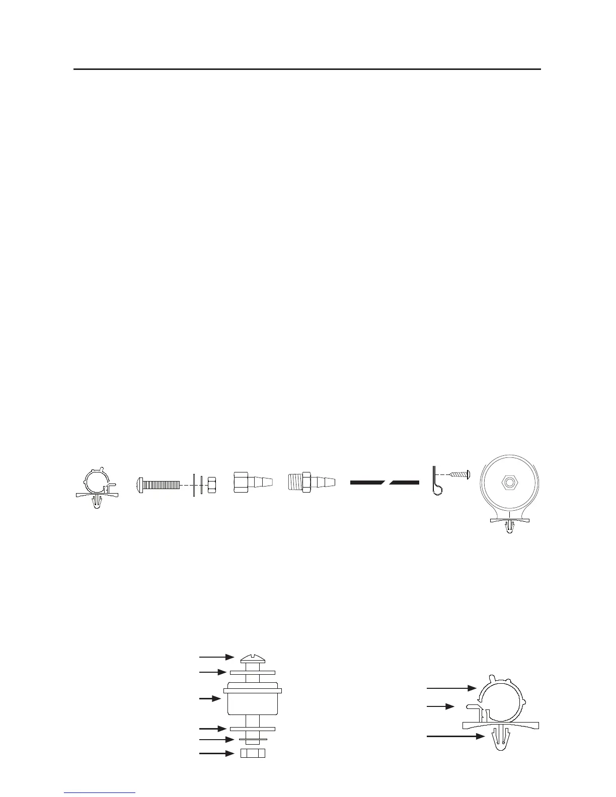
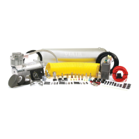
(Fig. 1) Standard 280C Air Compressor Kit Installation Parts List:
A.HoseBracket(1pc)
B.MountingBolts(4pcs)
C.FlatWashers(8pcs)
D.LockingWashers(4pcs)
E.Nuts(4pcs)
F.1/4”NPTFx3/8”BarbedFitting(1pc)
G.1/4”NPTMx3/8”BarbedFitting(1pc)
H.3/8”AirLine(1pc)
I.AirLineClips(3pcs)
J. Screws (3pcs)
K.RemoteInletAirFilterwithFilterElement(1pc)
(Fig. 2) Compressor
Mounting Hardware
B.MountingBolt
C.FlatWasher
D.LockingWasher
E.Nut
K. Vibration Isolator
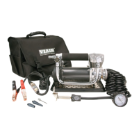
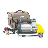
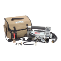
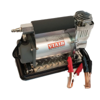
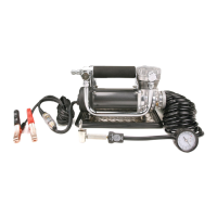
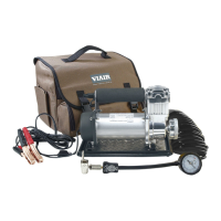
280C Air Compressor Kit
USER MANUAL
A
B C D E
F
G
I
J
K
(Fig. 3) Leader Hose Bracket
L.HoseClamp
M.ClampReleaseTab
N.SelfAnchoringPin
B
C
C
D
E
K
L
M
N
H