MOUNTING AND WIRING
1. Disconnectgroundcablefromvehicle’sbattery.
2. Temporarily position the air compressor in the location where it will be mounted.
3. Routegroundwiretothenegativepostofthebatteryortoanappropriategroundingpointand
cut ground wire to length as needed.
4. Mountaircompressorwiththefoursetsofbolts,nuts,washers,andlockingwashersprovided.
(SeeFig.2forMountingInstructions)Useofthreadsealantrecommended.
5. NOTE:Forremoteinletairlterinstallation,refertoinstructionsincludedintheRemoteInletAir
FilterPack.
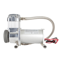
6. Thisaircompressormaybeequippedwithaheavydutyheatresistantleaderhose.Thisleader
hoseisdesignedtoprolongthelifeofyourairline.Donotremovethisleaderhosefromair
compressor. (Not applicable to P/N 32534)
7. IMPORTANT:Pleasenote,theleaderhosethatmaybeequippedwithyourcompressormay
alsohaveabuilt-ininlinecheckvalve.Donotremoveinlinecheckvalvefromleaderhoseif
soequipped.
8. Selectaproperlocationtomountleaderhosewithhosebracketprovided.Avoidlocations
where leader hose may become tangled with wires and other hoses.
9. Tomounthosebracket,drillholewith3/16”drillbitandpushself–anchoringhosebracketpin
intohole.Routeleaderhosethroughhosebracketandsecurehosebypressingbracketclamp
into locked position.
10.Toremovehosefromthehosebracket,simplypressdownonthehoseclampreleasetabto
releasebracketclamp.(Fig.3)
11.Connectcompressor’spositiveleadwiretooneoftheleadsofyourpressureswitch.
12.Makesurethatyourcompressorsetupisproperlyfused.Forappropriatefusesize,refertoamp
drawofcompressorinthespecicationssectionofthismanual.
13.Alwayslocatefuseascloseaspossibletopowersource.
14.Beforeconnectingtopowersource,re-checktomakesurethatallconnectionsare
made properly.
15. Connect and test compressor system by running the compressor for a short time to build up
pressure in your air tank.
16.Onceairpressurereachespresetcutoutpressureofyourpressureswitch,thecompressorwill
shut off. Inspect all air line connections for leaks with soap and water solution. If a leak is
detected,theairlinemaynotbecutsquarelyorpushedallthewayin.
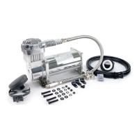
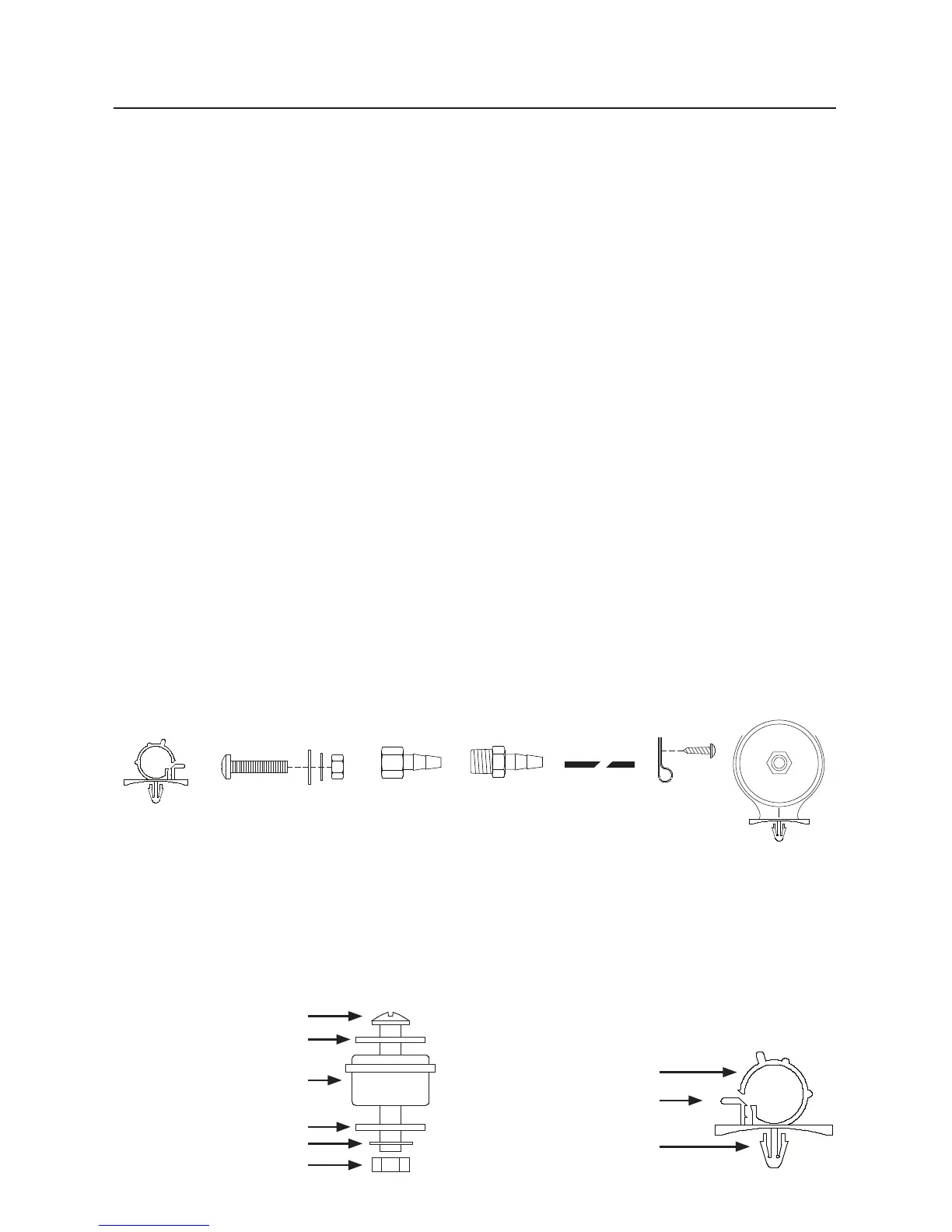
(Fig. 1) 325C / 350C / 400C / 450C Compressor Installation Parts List:
A.HoseBracket(1pc) - N/A 32534
B.MountingBolts(4pcs)
C.FlatWashers(8pcs)
D.LockingWashers(4pcs)
E.Nuts(4pcs)
F.1/4”NPTFx3/8”BarbedFitting(1pc) - N/A 32534
G.1/4”NPTMx3/8”BarbedFitting(1pc) - N/A 32534
H.3/8”AirLine - N/A 32534
I.AirLineClips(3pcs) - N/A 32534
J.Screws(3pcs)- N/A 32534
K.RemoteInletAirFilterwithFilterElement(1pc)- N/A 32534
(Fig. 2) Compressor
Mounting Hardware
B.MountingBolt
C.FlatWasher
D.LockingWasher
E. Nut
K. Vibration Isolator
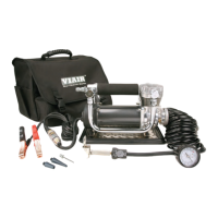
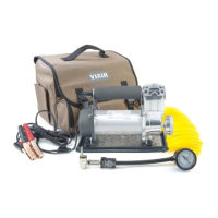
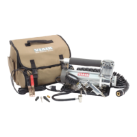
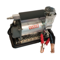
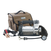
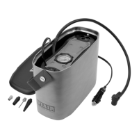
USER MANUAL
325C - 350C - 400C - 450C COMPRESSOR KIT
B
A
C D E
F
G
I
J
K
(Fig. 3) Leader Hose Bracket (N/A 32534)
L.HoseClamp
M.ClampReleaseTab
N.Self-AnchoringPin
B
C
C
D
E
K
L
M
N
H
 Loading...