Do you have a question about the Viavi IFR 6000 and is the answer not in the manual?
Provides an overview of the test set's general capabilities and primary functions.
Guides operators through initial setup and basic operations of the IFR 6000.
Details the self-test procedures for quick performance evaluation and troubleshooting.
Explains how to operate the IFR 6000 for various testing modes like XPDR, ADS-B, DME, TCAS, and TIS.
Covers the general installation steps, battery operation, charging, and safety precautions for the test set.
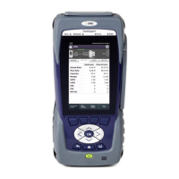
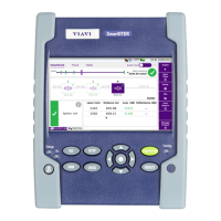
Identifies and describes the front panel controls, connectors, and indicators of the IFR 6000.
Details the self-test procedures for quick performance evaluation and troubleshooting.
Explains how to operate the IFR 6000 for various testing modes like XPDR, ADS-B, DME, TCAS, and TIS.
Lists the output frequency, level, pulse spacing, and width specifications for the DME signal generator.
Details the RF output frequency, level, and pulse spacing specifications for transponder mode testing.
Specifies output frequency, level, pulse spacing, and amplitude parameters for TCAS mode signal generation.
Provides specifications for the UAT RF signal generator, including output frequency, level, modulation, and UUT measurements.
Covers miscellaneous specifications including I/O ports, test antenna, time base, battery, input power, fuse requirements, environmental conditions, and physical characteristics.
Outlines the procedures and conditions for returning test sets to the factory for calibration, service, or repair, including authorization and tagging requirements.
Provides step-by-step instructions for properly repacking the test set into its shipping container to ensure protection during transit.
Lists the pin assignments and signal types for the various I/O connectors on the IFR 6000, including GPS, Video, DC Power, RF I/O, ANT, and REMOTE.
Provides a detailed pin-out table for the 44-pin REMOTE connector, specifying signal names, types, and descriptions for each pin.
Lists the factory and power-up default settings for general parameters like Power Down timeout, ERP units, and Remote Operation.
Details factory and power-up presets for XPDR screen parameters, including antenna selection, RF port, range, height, cable loss, and gain.
Outlines factory and power-up presets for DME screen parameters such as RF Port, Antenna Range, Ident Tone, Cable Loss, and Gain.
Shows factory and power-up settings for DME screen fields including VOR/Freq/Chan, RF Level, Range, Rate, % Reply, Echo, Ident, and Squitter.
Lists factory and power-up presets for fields displayed on the XPDR Auto Test Screen, such as Config, Antenna, Level, Replies, and Frequency.
Details factory and power-up presets for TCAS setup parameters including RF Port, Antenna Range/Height, UUT Address, Cable Loss/Gain, Squitter, Alt Reporting, Displayed Alt, and Test Set AA.
Shows factory and power-up settings for TCAS screen parameters such as Scenario, TCAS Type, Reply, Intruder Type, Range, Altitude, and Alt Rate.
Lists factory and power-up presets for ADS-B setup parameters including Position Decode, LAT/LONG, ADS-B GEN/MON, and GICB.
Displays factory and power-up presets for the ADS-B GEN BDS 0,5 screen, detailing Type, DF, AA, Period, LAT/LONG, POS, SAF, etc.
Lists factory and power-up presets for the ADS-B GEN BDS 0,6 screen, covering Type, DF, AA, Period, Movement, T, and HDG.
Outlines factory and power-up presets for the ADS-B GEN BDS 0,8 screen, including Type, DF, Count, AA, Period, Flight ID, Emit Cat Set, and Emit Cat.
Details factory and power-up presets for the ADS-B GEN BDS 0,9 screen, covering Type, DF, AA, Period, E-W Velocity, NACV, N-S Velocity, HDG, Subtype, Vert Rate, GEO ALT DIFF FROM BARO, Source, Intent Change, Airspeed, Airspeed Type, and IFR CAP ADS-B/CLASS A1.
Lists factory and power-up presets for the ADS-B GEN BDS 6,1 screen, including Type, DF, AA, Period, Emergency/Prior Code, Reserved, and Subtype.
Outlines factory and power-up presets for the ADS-B GEN BDS 6,2 screen, covering Type, DF, AA, Period, Vert Data/Source Info, Targ Alt Cap, Vert Mode Ind, SIL, Targ Alt Type, Nic Baro, Targ Alt, Targ Hdg, TCAS/ACAS Operational, RAA, Horiz Data Aval/Source Ind, Horiz Mode Ind, NAC, and Emerg/Prior Code.
Details factory and power-up presets for the ADS-B GEN BDS 6,5 screen, including Type, DF, AA, Period, Subtype, NAC, BAQ, SIL, TC, CDTI, ARV, TS, RA, Ver Nbr, Not-TCAS, Oper Mode Subfield, Nic Baro, Horiz Ref Dir, Ident, Trk/Hdg, NIC, Length/Width, Rec ATC Serv, and B2 Low.
Lists factory and power-up presets for TIS setup parameters such as RF Port, Antenna Range/Height, Dir Cable Loss/Ant Cable/Ant Cable Loss, Ant Gain, UUT Address, and Manual AA.
Shows factory and power-up settings for TIS screen fields including Targets, UUT HDG, BRG, RNG, ALT, ALT Rate, and HDG.
Displays factory and power-up presets for the UAT FIS-B screen, including Report, STN, Day/Time, Data, GND LAT, LON, and Slot ID.
Lists factory and power-up presets for the UAT TIS-B screen, covering Targets, UUT HDG, BRG, RNG, ALT, HDG, UUT ALT, UUT LAT, UUT LON, and TIS-B Site ID.
Details factory and power-up presets for the UAT ADS-B screen, including Targets, UUT HDG, BRG, RNG, ALT, HDG, UUT ALT, UUT LAT, and UUT LON.
Describes the USB Host connector pinout, including VBUS_DN1, H_D-, H_D+, and GND_DN1 signals.
Details the USB Device connector pinout, specifying VBUS_UP, D_D-, D_D+, and GND_UP signals.
Provides the pinout for the Altitude Encoder connector, listing pins A1 through D2 and GND.
Outlines the pinout for the AUX IN connector, including REM_IN1 through REM_IN4, GND, and DNU signals.
Details the pinout for the RS-232 connector, specifying HOST_TXD, HOST_RXD, GND, HOST_CTS, and HOST_RTS signals.
Describes the AUX OUT connectors (1-4) and their signal types, including Mode S Interrogation Trigger, ATCRBS Interrogation Trigger, SYNC, and Not Used.
Provides the detailed pin-out table for the 44-pin REMOTE connector, covering USB, RS-232, and Altitude Encode signals.
Lists TX Power, RX MTL, and TX Freq specifications for various ANT/DIR configurations under FAR 43.
Details TX Power, RX MTL, and TX Freq specifications for various Port Configurations and DIR w/ Coupler Configurations under MOD 43.
Explains the primary goals of Mode S, including aircraft surveillance and communications for dense traffic environments.
Describes the structure of Mode S messages, including Address/Parity, Surveillance, and Data Link Communications.
Outlines signal formats for uplink and downlink messages, referencing RTCA DO-181 and DO-185 standards for details.
| Brand | Viavi |
|---|---|
| Model | IFR 6000 |
| Category | Test Equipment |
| Language | English |