EasyManua.ls Logo

Viavi Smart Class 4800 - User Manual

Viavi Smart Class 4800
7 pages
Print Icon
To Next Page IconTo Next Page
Loading...
Smart Class 4800/4800P Quick Start Guide
July 2017 22122291, Rev. 000 Page 1
Smart Class 4800/4800P Quick Start
Guide
Thank you for purchasing a Smart Class 4800 or 4800P. This guide provides informa-
tion on how to get started testing with the instrument.
Unpacking and inspecting the components
Before using the instrument for the first time, please inspect the unit and components
to verify that no damage occurred during shipping.
When unpacking the components, verify that all the items you ordered are included in
the package. Accessories may be shipped in a separate box. After you unpack the
components, examine the connectors, ports, LEDs, and screen for damage. Be sure to
check the top, bottom, and front panels. If you find damage, contact Viavi Customer
Care at 1-844-GO-VIAVI (+1-844-468-4284) or at www.viavisolutions.com
. If you don’t
find any damage, consider saving the box and packing materials.
About the Smart Class 4800 and 4800P
The Smart Class 4800 and 4800P instruments are designed to be rugged, portable,
battery-operated test solutions that facilitate the quick turn-up and troubleshooting of
multiple services and network elements in the Metro and Core network.
Figure 1 Smart Class 4800
Question and Answer IconNeed help?

Do you have a question about the Viavi Smart Class 4800 and is the answer not in the manual?

Summary

Unpacking and Inspecting Components

About the Smart Class 4800 and 4800 P

Instrument Operation

Turning the Instrument On or Off

Instructions for powering the instrument on and off, including shutdown procedures.

Charging the Battery

Details on how the instrument's battery is charged via the AC adapter.

Exploring Hardware and Connectors

Navigating the User Interface

System and Test Icons

Explains the purpose of System and Test icons for settings and applications.

Menu Bar

Outlines the icons available in the menu bar for navigation and functions.

User Interface Components and Settings

Quick Config Settings

Describes quick configuration settings for test applications.

Test Tabs and Status

Explains the test tabs and how test status is displayed.

Application Buttons and Message Bar

Details the function of application buttons and the message bar.

User Interface Panels and Results

LED Panel

Explains the function of LEDs for indicating signal status and events.

Actions Panel

Describes the Actions Panel and its context-dependent buttons.

Results Buttons and Windows

Details how to select and view test results using buttons and windows.

Additional Documentation

Overview

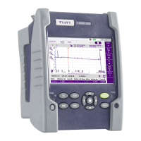
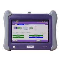
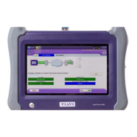
The Smart Class 4800 and 4800P are rugged, portable, battery-operated test solutions designed to facilitate the quick turn-up and troubleshooting of multiple services and network elements within Metro and Core networks. These instruments are used to set up, configure, and display test results for various network tests.

Function Description:

The primary function of the Smart Class 4800/4800P is to provide comprehensive testing capabilities for network services. This includes, but is not limited to, Ethernet, Fibre Channel, SONET/SDH, OTN, and PDH testing. The device allows users to perform various tests, analyze network performance, and identify issues. It supports the configuration of different test applications and displays real-time results, aiding in the efficient deployment and maintenance of network infrastructure.

Important Technical Specifications:

While specific detailed technical specifications like exact data rates or port types are not fully enumerated in the provided document, the manual indicates support for:

  • Ethernet: 1GigE Layer 2 Traffic Term, 10/100/1000 Ethernet, and potentially Layer 4 Multiple Streams Ethernet applications.
  • Optical Rates: The instrument supports testing for optical rates, implying the use of SFP connectors and laser/Tx signal control.
  • Connectivity: Features internal connectors and SFP connectors for connecting to circuits. The SC 4800P model specifically shows 10/100/1000 and SFP ports, along with E1/T1 interfaces.
  • Power: Operates on battery power or via an AC power adapter.
  • Display: Features a graphical user interface with a main screen for displaying test results, system settings, and test configurations.
  • Storage: The device saves current settings upon proper shutdown.

Usage Features:

  • Powering On/Off: The instrument is turned on or off by pressing the ON/OFF key. A short press (less than one second) turns it on, illuminating the power key green. To power down, the ON/OFF key must be pressed for one second, followed by selecting "Yes" on a confirmation message. This process saves current settings. A hard shut-down (pressing the power button for more than four seconds) does not save settings.
  • User Interface Navigation: The user interface is organized with several key elements:
    • System Icon: Provides access to system settings such as date, time, and file management.
    • Test Icon: Used to access various test applications.
    • Test Tabs: Appear near the top of the Main screen and display quick configuration settings relevant to the selected test application (e.g., Auto Negotiate, Test Mode, Frame Size for Ethernet tests).
    • Test Status: Located in the upper left, it indicates the status of the currently selected test using icons (e.g., "Play" for running, "Pause" for delayed-start, "Stop" for stopped).
    • Message Bar: Displays the current test application and port selection, along with other brief messages (e.g., successful loop-ups). A log of messages can be viewed by selecting the message area.
    • Application Buttons: Located on the right side of the GUI, these buttons provide access to setup screens, allow restarting tests, and perform other functions specific to the test application. The "Setup/Results" button toggles between setup and result screens. A "Restart" button is available to restart a test and clear results. Additional buttons, like a "Toolkit" button for running scripts, may appear depending on the selected application.
    • LED Panel: Positioned to the left of the Results Windows, this panel uses LEDs to indicate signal presence, pattern synchronization, and other key events during tests. Round LEDs show the current state, while square LEDs show the historical state. Green indicates expected events, yellow indicates events warranting investigation, and red indicates errors, anomalies, alarms, or defects. The panel can be collapsed or expanded by tapping its name.
    • Actions Panel: Appears under the LED display after a test application is selected. It contains tabs with buttons required to perform the test, which vary by application (e.g., start/stop Ethernet traffic, start/stop local loopback). A blinking circle on a tab indicates required user action. For optical rate tests, a "Laser / Tx Signal" tab appears, allowing SFP connector selection and laser control.
    • Results Buttons (Group and Category): Located at the top of each result window, these buttons allow users to select the type of results to observe (e.g., Summary results) and specific result categories. This enables viewing multiple sets of results simultaneously in different panes.
    • Results Windows: Display test results. Errors are highlighted in red, while other results appear in black. The layout of these windows can be changed via the "View" menu, which also allows showing only test results on the main screen.
  • Battery Charging: The battery charges automatically when the unit is connected to power using the AC power adapter.

Maintenance Features:

  • Inspection: Before initial use, users are instructed to inspect the unit and components for any shipping damage, including connectors, ports, LEDs, screen, and front/top/bottom panels.
  • Customer Support: In case of damage, users should contact Viavi Customer Care.
  • Documentation: The device comes with additional documentation on a USB memory stick, including:
    • T-BERD/MTS/SC Getting Started Guide
    • T-BERD/MTS/SC Ethernet and Fibre Channel Testing Manual
    • T-BERD/MTS/SC SONET/SDH, OTN and PDH Testing Manual These manuals provide detailed information on setup parameters, test result descriptions, and general usage of the T-BERD/MTS/SC family of testers.
  • Packing Materials: Users are advised to consider saving the box and packing materials for potential future use (e.g., shipping or storage).

Viavi Smart Class 4800 Specifications

General IconGeneral
BrandViavi
ModelSmart Class 4800
CategoryTest Equipment
LanguageEnglish

Related product manuals