EasyManua.ls Logo

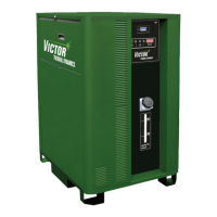
Victor ULTRA-CUT 100 User Manual

Victor ULTRA-CUT 100
202 pages
To Next Page IconTo Next Page
Page #1 background imageLoading...
Page #1 background image
VictorThermalDynamics.com
100 200 400300
400V
ULTRA-CUT 100,
200, 300, 400 XT
PLASMA CUTTING SYSTEM
Operating
Manual
Revision: AF Issue Date: October 2, 2014 Manual No.: 0-5264

Table of Contents

Questions and Answers:

Victor ULTRA-CUT 100 Specifications

General IconGeneral
Efficiency85%
Insulation ClassH
Output Current Range20 - 100 A
Duty Cycle60% @ 100 A
Gas TypeAir or Nitrogen
Gas Flow Rate190 lpm
Protection ClassIP23
No Load Voltage300V

Summary

General Information

Notes, Cautions, and Warnings

Explains the usage of notes, cautions, and warnings to highlight important information within the manual.

Important Safety Precautions

Details critical safety measures for operating plasma arc equipment, including hazards and protective actions.

Specifications

Specifications & Electrical Requirements

Details electrical requirements, duty cycle, operating range, and cooling specifications for each model.

Installation

Installation Requirements

Outlines necessary requirements for electrical supply, gas, and water systems during installation.

Ground Connections

Details procedures for establishing proper star ground connections for EMI reduction.

Set Switches on the Command - Control Module

Explains how to set the switches on the Command-Control Module for system configuration.

Operation

System Operation

Details the step-by-step procedure for starting and operating the plasma cutting system.

Power Supply Status Codes

Lists and explains the meaning of various status codes displayed by the power supply.

Maintenance

Replacement Assemblies & Parts

Torch Maintenance

Coolant Leak Trouble-Shooting

A flowchart to diagnose and resolve coolant leaks from the torch head.

Advanced Troubleshooting

Status codes

Explanation of status codes related to plasma process, power supply, and cooling systems.

Troubleshooting Pilot Board problems

Guidance for diagnosing issues related to the Pilot board and its associated LEDs.

Pilot Ignition Failure

Troubleshooting steps for code 102: Pilot Ignition Failure.

Transfer Lost

Troubleshooting steps for code 104: Arc transferred to metal then went out.

Tip to Electrode Voltage Fault

Troubleshooting steps for code 108: Tip to Electrode Voltage Fault.

Missing AC Phase

Troubleshooting steps for code 201: Missing AC Phase.

DC Output Low

Troubleshooting steps for code 205: DC Output Low.

Unexpected Current in the Work Lead

Troubleshooting steps for code 207: Unexpected current in the work lead.

Unexpected current in Pilot Circuit

Troubleshooting steps for code 208: Unexpected current in pilot circuit.

Inverter Fault

Troubleshooting for codes 247-252: Inverter Fault.

Gas Controls Status and Communication Protocol

Gas Control Communication Fault

Troubleshooting for code 301: Gas Control Communication Fault.

Gas Pressure fault

Troubleshooting for code 303: Gas Pressure fault.

Liquid Cooling System Codes

Coolant Level Low

Troubleshooting for code 401: Coolant Level Low.

Low coolant Flow

Troubleshooting for code 402: Low coolant Flow.

Coolant overheated

Troubleshooting for code 403: Coolant overheated.

Coolant System Not Ready

Troubleshooting for code 404: Coolant System Not Ready.

CANBUS Failure to Acknowledge fault

Troubleshooting for code 501: CANBUS Failure to Acknowledge fault.

CCM and Program Updates

Related product manuals