EasyManua.ls Logo

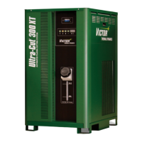
Victor ULTRA-CUT 300 XT User Manual

Victor ULTRA-CUT 300 XT
204 pages
To Next Page IconTo Next Page
Page #1 background imageLoading...
Page #1 background image
VictorThermalDynamics.com
ULTRA-CUT 300 XT
PLASMA CUTTING SYSTEM
AUTOMATED GAS CONTROL
Operating
Manual
Revision: AE Issue Date: May 2, 2014 Manual No.: 0-5305
8
4

Table of Contents

Questions and Answers:

Victor ULTRA-CUT 300 XT Specifications

General IconGeneral
Input Frequency50/60 Hz
Efficiency85%
Insulation ClassH
Gas TypeNitrogen
Open Circuit Voltage300V
Gas Pressure65-75 psi (4.5-5.2 bar)

Summary

SECTION 1: GENERAL INFORMATION

1.01 Notes, Cautions and Warnings

Explains the use of notes, cautions, and warnings to highlight important information.

1.02 Important Safety Precautions

Details hazards and essential safety practices for plasma arc equipment operation.

1.03 Publications

Lists relevant standards and publications for safety and practices.

1.07 Declaration of Conformity

Declares the product's compliance with standards and technical requirements.

1.08 Statement of Warranty

Details the limited warranty terms, conditions, and duration for the product.

SECTION 2: SPECIFICATIONS

2.01 General Description Of The System

Outlines the components included in a typical Ultra-Cut XT system configuration.

2.06 Specifications & Electrical Requirements

Provides detailed technical specifications and electrical requirements for the 300 Amp system.

2.09 Gas Requirements

Details the required gas quality, pressures, and flow rates for system operation.

2.10 Gas Applications

Lists recommended gas types and applications for cutting various materials.

2.11 XT Torch Specifications

Lists technical ratings and gas specifications for the XT torch.

SECTION 3: INSTALLATION

3.01 Installation Requirements

Outlines requirements for electrical supply, gas supply, and cooling system.

3.04 Leads and Cables All Amperage

Details various leads and cables used in the system, their identification, and purpose.

3.08 Ground Connections

Details preferred grounding arrangements and procedures for system grounding.

3.11 Handling and Installation of Fiber Optics

General information and guidelines for handling and installing fiber optic cables.

3.19 Install TSC-3000 Touch Screen Control

Provides instructions for selecting a location and installing the TSC-3000 Touch Screen Control.

3.21 Connecting Torch

Step-by-step instructions for connecting the plasma torch assembly.

3.24 Complete the Installation

Final steps for completing the installation, including filling the coolant tank.

SECTION 4: OPERATION

4.01 Power Supply Control Panel

Identifies and explains the indicators and controls on the power supply panel.

4.02 System Operation

Provides general operating information and safety precautions for the system.

4.04 TSC-3000 Initial Setup ONLY

Guides through the initial setup steps required before first operation of the TSC-3000.

4.05 TSC-3000 Selecting New Process

Details how to select a new cutting process based on material, thickness, and amperage.

4.09 Sequence of Operation

Explains the step-by-step sequence for operating the DFC 3000 with TSC 3000.

4.10 Gas Selection

Discusses the selection of appropriate plasma and shield gases for different cutting applications.

4.11 CCM Status Codes

Lists and explains CCM status codes, their messages, and remedies for faults.

SECTION 5: MAINTENANCE

5.01 General Maintenance

Outlines a periodic maintenance schedule for the power supply.

5.02 External Coolant Filter Cleaning Procedure

Step-by-step instructions for cleaning the external coolant filter.

5.03 Coolant Replacement Procedure

Provides instructions for replacing the coolant in the system.

SECTION 6: REPLACEMENT ASSEMBLIES & PARTS

6.04 Leads And Cables All Amperages

Illustrates and identifies various leads and cables used in the system with part numbers.

6.10 DFC-3000 Automated Gas Control System Replacement Components

Lists replacement components for the DFC-3000 Automated Gas Control System.

6.11 DMC-3000 Gas Control Module Replacement Parts

Details replacement parts for the DMC-3000 Gas Control Module.

6.14 Remote Arc Starter (RAS-1000 XT) Replacement Parts

Lists replacement parts for the Remote Arc Starter (RAS-1000 XT).

SECTION 7: TORCH MAINTENANCE

7.04 Torch Consumables Installation

Step-by-step instructions for installing torch consumables correctly.

7.05 Coolant Leak Trouble-Shooting

Provides a flowchart for troubleshooting coolant leaks from the torch head.

APPENDIX 1: CNC - Control Module PCB Connections

CNC functions

Explains the CNC I/O circuits and their galvanic isolation from the power supply.

J54 - Remote HMI & CNC COMM

Details the connections for the remote HMI and CNC communication ports.

APPENDIX 21: Schematic, DFC-3000 Auto Gas Box System

Appendix 24: Advanced Troubleshooting

System Overview

Provides an overview of the system's inverter modules and configurations.

Status codes.

Explains how status codes are displayed and categorized for the power supply.

Troubleshooting (General)

Provides general troubleshooting tips, including advice on meter probes.

101 Plasma Enable Is Disabled

Explains the cause and troubleshooting for code 101, indicating disabled plasma enable.

102 Pilot Ignition Failure

Details causes and troubleshooting steps for pilot ignition failures.

104 Transfer Lost

Details causes and troubleshooting for the arc transfer failing or being lost.

201 Missing AC Phase

Explains causes and troubleshooting for missing AC input phases.

205 DC Output Low

Details causes and troubleshooting for low DC output voltage from the system.

207 Unexpected Current in the Work Lead.

Explains causes and troubleshooting for unexpected current detected in the work lead.

208 Unexpected current in Pilot Circuit

Details causes and troubleshooting for unexpected pilot circuit current.

239 AC Voltage High

Explains causes and troubleshooting for high AC voltage conditions.

240 AC Voltage Low

Details causes and troubleshooting for low AC voltage conditions.

253-258 Inverter Over Temperature.

Explains causes and troubleshooting for inverter over-temperature conditions.

301 Gas Control Communication Fault

Explains causes and troubleshooting for gas control communication faults via fiber-optic.

401 Coolant Level Low

Explains causes and troubleshooting for low coolant level warnings and faults.

402 Low coolant Flow

Details causes and troubleshooting for low coolant flow conditions.

404 Coolant System Not Ready

Details causes and troubleshooting for the coolant system not being ready.

APPENDIX 25: PUBLICATION HISTORY

Related product manuals