EasyManua.ls Logo

Victor VC60B+ User Manual

Victor VC60B+
2 pages
To Next Page IconTo Next Page
Page #1 background imageLoading...
Page #1 background image
- 1 -
INSULATION TESTER
INSTUCTION MANUAL
GENERAL
This instrument adopts the DC Voltage convertor of low
consumption and high converter ratio inductance energy
storage, to change the 9V Voltage to 250V/500V/1000V DC
Voltage. It uses digital bridge to make the insulation
resistance measurement had the features of user-friendly,
high extent range, backlight display, data hold and auto
power off. The whole instrument is stylish and superior grade
in appearance and high stable in performance, it can be
operated by both hands through using a shoulder strap. It is
most suitable for the needs of insulation resistance check,
such as electric, cable, electrical and mechanical equipment,
telecommunication equipment and electrical facilities.
二、FRONT PANEL DESCRIPTION
1234Voltage selection switchAC750V/500V/250V/1000V.
5Resistance Range selection switchRANGE.
6Power switchauto-lock power switchPOWER.
7High voltage indicatorLED display.
8Measurement button.
9LCD displayDisplay the measured data and units
10Instrument model.
11L: Terminal for connecting the measured circuit.
12GTerminal for protection, connect the electrode wire of
protection loop to “G” terminal when the measured
object is required to add the protection loop to eliminate
the leakage effect.
13ACV: Input terminal of AC Voltage measurement.
14ETerminal for connecting the ground of the measured
object.
15Terminal of AC adaptor
三、TECHNIC PROPERTY
1General Property
1Display84.8×59.8mm LCD display, max.1999”。
2Over range indicatordisplay1”。
3Power5# battery LR6 (1.5V) ×6 (or external AC
adaptor), no battery indicator Auto power off
(approx. 15miutes after turning on)
4Power consumptionconsumption is less than 300mw
at unload measurement.
5 Operation environment Temperature 0°C 40°C.
Relative humidity 30%RH85RH.
6Dimension175(L) ×110(W) ×70(D) mm
7Weight630 g (including batteries).
2Technical property
Measured
voltage
250V±10%
500V±10%
1000V±10%
RANGE
0.1MΩ—
20MΩ
0.1MΩ—
50MΩ
0.1MΩ—
100MΩ
20MΩ—
500MΩ
50MΩ—
1000MΩ
100MΩ—
2000MΩ
Accuracy
±(4% of reading ± 2 digits
Shot current
1.8mA
1.8mA
1.6mA
Median
resistance
2 MΩ
2MΩ
5MΩ
Terminal
position
L . E
ACV750V Accuracy:±(1.0% of reading + 6 digits).
Terminal positionACV G
Input impedance 1MΩ。
Frequency response:( 50200Hz
NoteMedian resistance——to ensure that the voltage of
both sides of measurement is not less than 90% of lower
limit of resistance measurement of measurement voltage
normal value
四、OPERATION DESCRIPTION
1Open the battery case and set up 6pcs of 5# batteries
(see the following pictures), note the polarity of
batteries.
2Press the button ofPOWER.
3Select the right voltage (250V/500V/1000V/AC750V) according
to the requirement of measurement.
4Select the right range (RANGE) (except AC750V), according to
the requirement of measurement.
5Connect the electrode of the measured object to the relative
terminal of the instrument.
6When measuring cable, connect G Terminal to the protection
loop.
7Press the button of measurement and start it, turn the
knob right to lock the button; when the value is stable,
get the reading from LCD.
8Connect the input line “E” to the ground of the
measured object, and “L” to the circuit of the
measured object; require line “L” to hang in the air.
92000MΩ。When “1” is displayed, over range is indicated,
and should turn to the higher range to get reading;
When the range button is in position, it
expresses that the insulated resistance exceeds
2000MΩ.
10Hang the instrument on your neck to save your hands
Question and Answer IconNeed help?

Do you have a question about the Victor VC60B+ and is the answer not in the manual?

Victor VC60B+ Specifications

General IconGeneral
ModelVC60B+
CategoryDigital Multimeter
Diode TestYes
Continuity BuzzerYes
Transistor TestYes
Data HoldYes
Back LightYes
Power Supply9V battery (6F22)
DC Voltage200mV/2V/20V/200V/1000V
DC Current2mA/20mA/200mA/10A
AC Current200mA/10A
Resistance200Ω/2kΩ/20kΩ/200kΩ/2MΩ/20MΩ
Capacitance2nF/20nF/200nF/2μF/20μF
Temperature-20°C to 1000°C
Frequency20kHz ±(1.5%+5)
Safety StandardsIEC61010-1, CAT III 600V

Summary

GENERAL INSTRUMENT OVERVIEW

Instrument Features and Applications

Describes the DC voltage converter, user-friendly features, high range, backlight, data hold, and auto power off capabilities.

FRONT PANEL DESCRIPTION

Voltage Selection Switch

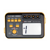
Selects the measurement voltage from 250V, 500V, 1000V DC, or AC750V.

Resistance Range Selection

Selects the resistance measurement range.

Power Switch

Auto-lock power switch for instrument operation.

High Voltage Indicator

LED display indicating high voltage status.

Measurement Button

Button used to initiate measurement.

LCD Display

Displays measured data, units, and status information.

Instrument Model Display

Shows the instrument model designation.

L Terminal

Terminal for connecting the measured circuit.

G Terminal (Protection)

Protection terminal for leakage effect elimination.

ACV Terminal

Input terminal for AC Voltage measurement.

E Terminal (Ground)

Terminal for connecting the measured object's ground.

AC Adaptor Terminal

Connection point for external AC power adaptor.

TECHNICAL PROPERTIES

General Properties

Covers display, over range, power, consumption, operation environment, dimensions, and weight.

Electrical Specifications

Details accuracy, input impedance, and frequency response for measurements.

OPERATION DESCRIPTION

Battery Installation

Instructions for opening the battery case and installing 6pcs of 5# batteries, noting polarity.

Power On and Setting Selection

Pressing the POWER button and selecting the appropriate voltage and range for measurement.

Connecting Measurement Leads

Connecting leads to the measured object's terminals and using the G terminal for protection.

Performing Measurement

Pressing the measurement button, locking it, and reading stable values from the LCD.

Interpreting Over-Range Readings

Understanding '1' display for over-range and using higher ranges or specific settings for >2000MΩ.

Convenient Usage Tip

Suggestion to hang the instrument on the neck to free up hands during measurement.

METHOD TO MEASURE THE INSULATED RESISTANCE

SAFETY NOTES

High Voltage Warning

Caution regarding high voltage at output terminals when voltage selection is not pressed.

Pre-Measurement Checks

Verifying voltage selection, ensuring object is discharged, and avoiding terminal contact during measurement.

Environmental Precautions

Keeping instrument away from high temperatures and direct sunlight to protect the LCD.

Battery Handling and Storage

Replacing batteries when low battery symbol appears and removing them for long-term storage.

Reading Stability and Interference

Connecting the 'G' terminal to the shield side for stable readings in noisy environments.

Test Lead Integrity

Using original silicone rubber test leads and advising against unauthorized changes.

AC Adaptor Usage

Note on battery disconnection when using AC adaptor and correct power supply method selection.

SETS OF INSTRUMENT

FAULT ELIMINATION

Troubleshooting Common Issues

Provides solutions for common faults like 'No display', 'symbol appearance', and 'Error value'.

Related product manuals