EasyManua.ls Logo

Victor 03 - User Manual

Victor 03
15 pages
Print Icon
To Next Page IconTo Next Page
Loading...
1
1.
1.
1.
1.
Safety
Safety
Safety
Safety
Information
Information
Information
Information
To
ensure the safety operation, the following signs are used only as
specified in this operation instruction.
Warning
Warning
Warning
Warning
A
warning shows that if the operation does not comply
with the following correct methods, it is possible to bring
hazards to the user or cause damage to the calibrator in
use. The warning also points out how to avoid the
accidents.
Caution
Caution
Caution
Caution
A
caution shows that if the operation does not comply
with the following correct methods, it is possible to cause
damage to the calibrator in use .the caution also points
out how to avoid maloperation.
Note
Note
Note
Note
A
note serves as a sign to remind the user that he must
understand the correct operation of the calibrator and its
characteristics.
T
o prevent the user and the calibrator from any electric shock and other
hazards, it is necessary to observe the following regulation;
warning
warning
warning
warning
I t is not allowed to operate the calibrator at the working field
where there exists flammable gas or explosive gas or vapor .It
is very dangerous to operate the calibrator in such a
surrounding.
N ever apply more than 30V between any two terminals, or
between any terminal and earth ground.
C
C
C
C
aution
aution
aution
aution
D
D
D
D
isassembly
isassembly
isassembly
isassembly
: No one is allowed to remove the split case (top &
bottom) of the calibrator except professionals.
I
I
I
I
n
n
n
n
use
use
use
use
: The calibrator can t perform both input and output
simultaneously. No direct connection can be made
between both input and output.
M
M
M
M
aintenance
aintenance
aintenance
aintenance
: Periodically wipe the case with a damp cloth and
detergent; do not use any corrosive solvents.
Question and Answer IconNeed help?

Do you have a question about the Victor 03 and is the answer not in the manual?

Summary

Safety Information and Symbols

Instrument Panel Layout and Function

Battery Replacement and Power Management

Battery Replacement Procedure

Step-by-step guide for replacing a low battery.

Output from Calibrator

Caution on Output Terminal Voltage

Warns against applying voltage to the output terminal.

Simulating Resistance or RTD Output

Explains how the calibrator simulates resistance and RTD output.

Calibrator Measurement

Warning on Voltage Limits

Warns against exceeding 30V for safety and device protection.

Caution on Input Terminal Limits

Warns against exceeding measuring range and heavy current on input.

Measuring Resistance and RTD

Explains the process of measuring resistance and RTD values.

Performance Capabilities

Output Function Specification

Details output specifications for OHM and RTD, including accuracy.

Input Function Specification

Details input specifications for OHM and RTD, including accuracy.

Calibration

Calibration Recommendation

Recommends annual calibration and lists standard equipment.

Caution During Calibration

Warns against overvoltage and short circuits during calibration.

Selecting Standard Equipment for Output

Lists standard equipment and accuracy for output calibration.

Selecting Standard Equipment for Input

Lists standard equipment and accuracy for input calibration.

Calibration Conditions and Procedure

Operating Output Calibration

Steps for calibrating output characteristics, focusing on OHM.

Resistance Output Calibration Steps

Input Calibration Procedure

Overview

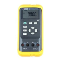
This document describes a calibrator device, providing details on its functions, technical specifications, usage, and maintenance.

Function Description

The calibrator is designed to simulate and measure Resistance Temperature Detectors (RTDs) and resistance (OHM). It can output RTD-simulating temperature signals or resistance values set by the user. For measurement, it can measure resistance and RTD values.

The device features an LCD display area that shows various symbols to indicate its operational state:

  • OUTPUT: Calibrator is in an output state.
  • INPUT: Calibrator is in an input state.
  • CAL: Calibrator is in a state of calibration.
  • 0 FS: Calibrator is in a calibration state, with the zero point or full scale point being calibrated.
  • Battery symbol: Battery is nearly used up and needs replacing.
  • Triangle symbol: Output digits need setting.
  • °C/°F: Units of current values for input or output.
  • ON: Signal of input or output is in a turn-on state.
  • Pt100, Cu50: Types of RTDs.

Important Technical Specifications

Output Function & Specification (applicable to temperature range from 18 to 28 °C, within one year after calibration):

Output Item Range Output Range Resolution Accuracy Remark
OHM 400 Ω 0.0 to 400.0 Ω 0.1 Ω ± 0.05% of set value ± 0.2 Ω ±1mA exciting current Notes 1 & 2
RTD Pt100 - 200.0 to 850.0°C 0.1°C ± 0.05% of set value ± 0.6°C ±1mA exciting current, use Pt100-385. measuring current 1mA Notes 1 & 2
RTD Cu50 - -50.0 to 150.0°C 0.1°C - ±1mA exciting current Notes 1 & 2

Input Function & Specification (applicable to temperature range from 18 to 28 °C, within one year after calibration):

Input Item Range Input Range Resolution Accuracy Remark
OHM 400 Ω 0.0 to 450.0 Ω 0.1 Ω ± 0.05% of means. value ± 0.2 Ω ±1mA means. current Notes 1 & 2
RTD Pt100 -200.0 to 850°C - 0.1°C ± 0.05% of set value ± 0.6°C ±1mA exciting current, use Pt100-385. measuring current 1mA Notes 1 & 2
RTD Cu50 -50.0 to 150.0°C - 0.1°C - ±1mA exciting current Notes 1 & 2

Notes for Specifications:

  • Note 1: without accessory lead resistance
  • Note 2: range of exciting current: 0.5mA to 2mA; max. output voltage: <2V
  • Note 3: temperature coefficient: ± 0.005% of range per °C for the temperature ranges from 0 to 18°C and from 28 to 50°C

General Specifications:

  • Power supply: single 9V battery (ANSI/NFDA 1604A or IEC6LR619V alkaline)
  • Battery life: ca. 25 hours
  • Max. permitted voltage: 30V (between any two terminals or between any terminal and earth ground)
  • Operating temperature: 0°C to 50°C
  • Operating relative humidity: ≤80% RH
  • Storage temperature: ≤-10°C to 55°C
  • Storage humidity: ≤90% RH
  • Size: 200×100×40 mm (with holster)
  • Weight: 550g (with holster)
  • Accessories: operation instruction, a set of CF-36 industrial test lead (with alligator clips)
  • Option: AC power-supply adapter (VCPS) and a set of CF-31-A industrial test lead (with probe clips)
  • Safety: certified as compliant to IEC1010 provisions (safety standard issued by International Electrotechnical Commission)

Usage Features

Safety Information:

  • Warning: Indicates potential hazards to the user or damage to the calibrator if operations are not followed correctly.
    • Do not operate in fields with flammable or explosive gas/vapor.
    • Never apply more than 30V between any two terminals or between any terminal and earth ground.
  • Caution: Indicates potential damage to the calibrator if operations are not followed correctly.
    • No one is allowed to disassemble the calibrator except professionals.
    • The calibrator cannot perform both input and output simultaneously.
    • No direct connection can be made between both input and output.
  • Note: Reminds the user to understand correct operation and characteristics.
    • Warm up for 5 minutes before operation to ensure accuracy.
    • Contact the manufacturer for higher accuracy requirements or if automatic reference-junction temperature compensation deviates.

Instrument Panel Layout and Function:

  • LCD display area: Shows measurement values, units, and operational status.
  • Power switch key: Turns the device on/off.
  • Input/Output switching key: Toggles between input and output modes.
  • FUN select key: Selects the function (e.g., resistance, RTD).
  • RANG select key: Selects the range or type (e.g., Pt100, Cu50).
  • °C/°F switching key: Selects temperature units.
  • Output digit select key (◀/►): Selects digits for setting output values.
  • Output value setting key (▲/▼): Changes the value of the set digits.
  • Zero reset key: Sets output directly to 000.0 °C.
  • Input terminal: For connecting to the device under test in input mode.
  • Output terminal: For connecting to the device under test in output mode.

Power-On/Off:

  • Press the power key to turn on.
  • Press and hold for one second to turn off.
  • Upon power-on, the calibrator performs a self-diagnosis and displays a full screen.
  • Power-on Note: To ensure correct operation, it's good practice to turn off the power supply for 5 seconds before restarting.

Automatic Power-Off:

  • Factory setting: Automatically cuts off power if no operation occurs within 10 minutes after power-on.
  • This function can be enabled or disabled by the user (refer to section 7 for setting).

Simulating Output from Resistance or RTD:

  • Connect test leads to the output jack of the calibrator and the input of the user's instrument.
  • Press INPUT/OUTPUT until "OUTPUT" appears on the display.
  • Press FUN to select resistance or RTD function.
  • For RTD, press RANG to select the type.
  • Use ◀/► to select digits and ▲/▼ to change values.
  • Press ZERO to set output to 000.0 °C.
  • Press °C/°F to select temperature units.
  • Resistance simulation Note: The calibrator produces simulated resistance up to 400 Ω. The calibrated device must provide an exciting current (0.5mA to 2mA). A 4-wire system is designed for resistance output; a 2-wire system may introduce an error (ca.0.1 Ω). Improper resistance may occur if capacitance between calibrator and tested instrument exceeds 0.1µf.

Calibrator Measurement (Input Mode):

  • Connect test leads to the input jack of the calibrator and the output of the user's instrument.
  • Press INPUT/OUTPUT until "INPUT" appears on the display.
  • Press FUN to select the desired measurement function (resistance or RTD type).
  • For RTD, press RANG to select the corresponding type.
  • The display shows "000.0" then the measured result. If the value exceeds the range, "-OL-" is displayed.
  • Press °C/°F to select temperature units.
  • Warning: Never apply more than 30V between any two terminals or between any terminal and earth ground during measurement.
  • Caution: Do not apply voltage exceeding the measuring range to the input terminal or heavy current, as this can damage the calibrator or the instrument being measured.

Calibration Procedure:

  • The calibrator should be calibrated once a year.
  • Ambient Condition for Calibration:
    • Temperature: 23℃ ± 1℃
    • Relative humidity: 45 to 75% RH
    • Warm-up: Standard equipment must be warmed up. Do not connect the calibrator to power until it has been exposed to ambient conditions for 24 hours. Set calibrator to non-automatic shutdown and warm up for 0.5 hour.
    • Power supply for calibration: Battery needs replacing with a new one.
  • Operating Output Calibration (OHM/400):
    • Connect the calibrator to a digital meter and standard source.
    • Press FUN & RANG, then POWER to enter calibration mode.
    • Set digital meter and standard source to corresponding range (+1mA output).
    • Use ◀/► and ▲/▼ to match calibrator indication with digital meter reading.
    • Press ZERO to store the calibrated point (display flashes).
    • Press RANG to display "CAL FS", "CAL 0 FS", "CAL 0", "CAL FS", "CAL 0 FS" (with '-' for negative values), repeating steps 4 and 5 for each point.
    • Set standard source to -1mA output for negative calibration points.
    • Exciting current Note: Exciting current direction must align with the calibration point, otherwise storage is invalid.
  • Operating Input Calibration (OHM/400):
    • Connect the calibrator to a standard source.
    • Press FUN to enter input calibration mode.
    • Set standard source to corresponding range and output.
    • With output stabilized, press ZERO when display flashes to store the calibrated point.
    • Cut off power to exit calibration state.

Maintenance Features

  • General Maintenance: Periodically wipe the case with a damp cloth and detergent. Do not use any corrosive solvents.
  • Battery Replacement:
    • Turn off the calibrator and remove test leads.
    • Remove the holster.
    • Open the battery cover by releasing the lock.
    • Replace the used battery with a new one.
    • Put the battery cover back and lock it, then replace the holster.
    • Warning: Power supply must be shut down and test leads removed before replacing the battery.

Victor 03 Specifications

General IconGeneral
BrandVictor
Model03
CategoryMeasuring Instruments
LanguageEnglish

Related product manuals