2) P ress the key 〔 FUN
FUN
FUN
FUN
〕 & 〔 RANG
RANG
RANG
RANG
〕 first, and then press the
key 〔 POWER
POWER
POWER
POWER
〕 to enter the calibrator in a state of calibrating th e
resistance output when the display indicates the symbols
‘ OUTPUT ’ , ‘ CAL 0 ’ , ‘ ON
’
and the unit ‘ Ω ’ .
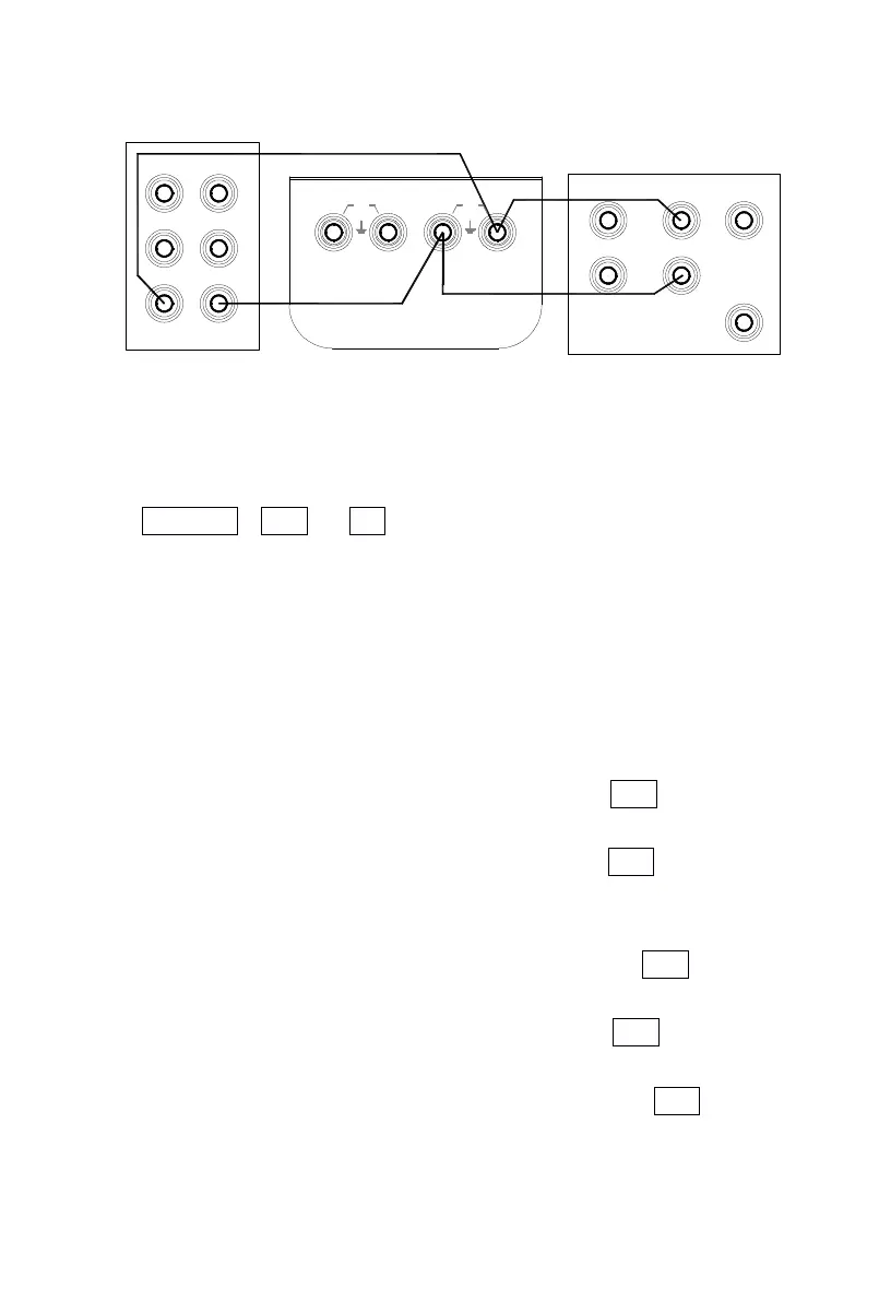
3) S et the digital meter and the standard source to a corresponding
range, and then set the standard source to +1mA output.
4) W ith the output stabilized, operate the
keys
〔
〕
/
〔
〕
and 〔
〕
/ 〔 〕 to set the indication of the calibrator in identity with the
reading of the digital meter.
5) P ress the key 〔 ZERO
ZERO
ZERO
ZERO
〕
and the display will flash, denoting that t he
calibrated point has been stored.
6) P ress the key 〔 RANG
RANG
RANG
RANG
〕
to display the symbol ‘ CAL FS ’ . With t he
output stabilized, repeat the operation of steps 4 and 5.
7) P ress the key 〔 RANG
RANG
RANG
RANG
〕
to display the symbol ‘ CAL 0 FS ’ . With t he
output stabilized, repeat the operation of steps 4 and 5.
8) S et the standard source to -1mA output.
9) P ress the key 〔 RANG
RANG
RANG
RANG
〕 to display the symbol s ‘ CAL 0 ’ , ‘ -
’
. With
the output stabilized, repeat the operation of steps 4 and 5.
10) P ress the key 〔 RANG
RANG
RANG
RANG
〕
to display the symbol s ‘ CAL FS ’ , ‘ -
’
. W ith
the output stabilized, repeat the operation of steps 4 and 5.
11) P ress the key 〔 RANG
RANG
RANG
RANG
〕 to display the symbol s ‘ CAL 0 FS ’ , ‘ -
’
.
With the output stabilized, repeat the operation of steps 4 and 5.
AUX
Hi
NORMAL
Lo
30V
MAX
30V
MAX
Lo
Lo Hi
Hi
OUTPUT
INPUT
SCOPE
TRIG
OUT
digital meter (1281 )
GUARD
I+
I-
LoHi
standard soure (
5520A )
 Loading...