Note
Note
Note
Note
E
E
E
E
xciting
xciting
xciting
xciting
current:
current:
current:
current:
The direction of the exciting current must be in
line with the calibration point, otherwise the
display will not flash, denoting that the storing
of calibrated point is invalid.
9.4
9.4
9.4
9.4
Operating
Operating
Operating
Operating
Input
Input
Input
Input
Calibration
Calibration
Calibration
Calibration
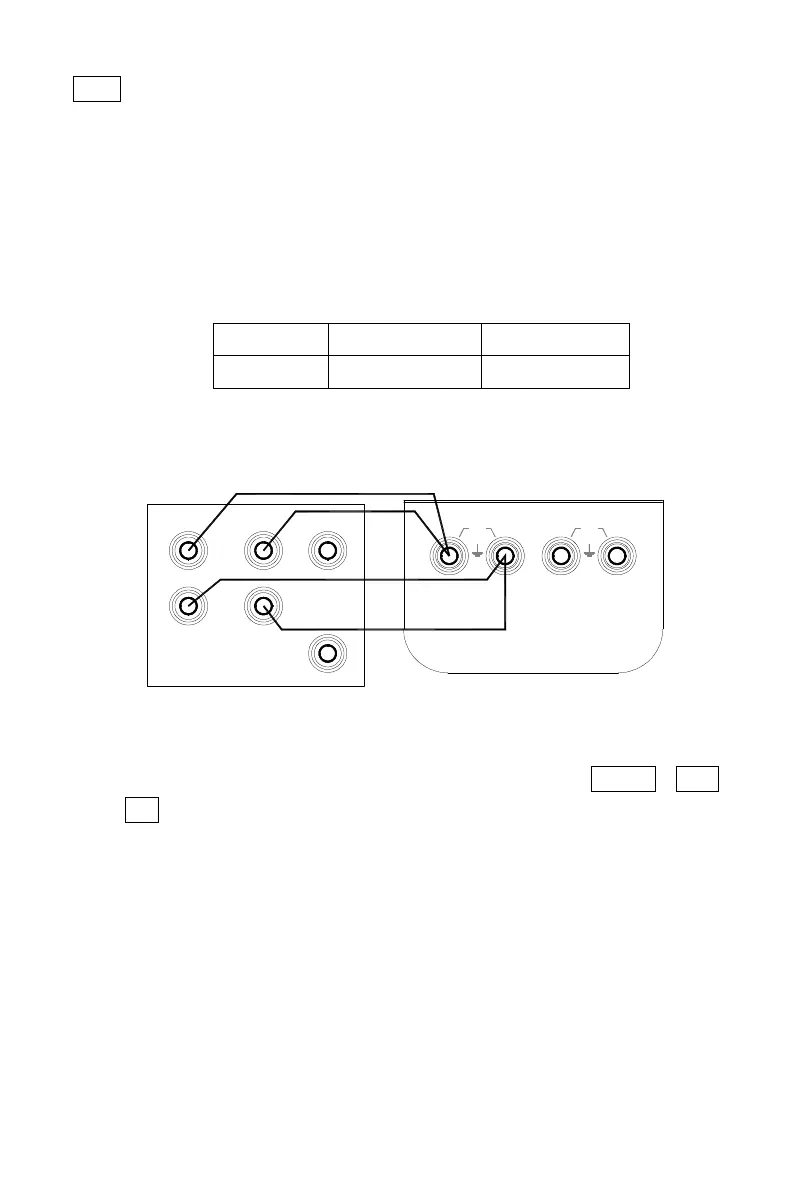
O perating calibration in order of items and calibration points in the
following table:
1) T he calibration wiring is shown in the following diagram:
2) P ress the key 〔 FUN
FUN
FUN
FUN
〕 to the calibrator in a state of the 400 Ω inpu t
calibration .Then the display indicates the symbols ‘ INPUT ’ , ‘ CAL 0 ’ ,
‘ ON ’ , ‘ 400 Ω ’ .
3) Set the standard source to a corresponding range.
4) S et the standard source output to the indication of the calibrator
.with the output stabilized ,press the key 〔 ZERO
ZERO
ZERO
ZERO
〕
when the displ ay
starts flashing ,denoting that the calibrated point has been stored.
5) N ow cut off the power supply again and the calibrator will quit the
calibration state.
10.
10.
10.
10.
Points
Points
Points
Points
for
for
for
for
Attention
Attention
Attention
Attention
to
to
to
to
Use
Use
Use
Use
of
of
of
of
Operation
Operation
Operation
Operation
Item
Item
Item
Item
.No
.No
.No
.No
I
I
I
I
nput
nput
nput
nput
Range
Range
Range
Range
C
C
C
C
alib.
alib.
alib.
alib.
Point
Point
Point
Point
TRIG
OUT
Lo
INPUT
Hi
AUX
SCOPE
Hi
NORMAL
Hi
30V
MAX
Lo
30V
MAX
Lo
OUTPUT
standard source ( 5520A )
 Loading...