13.4.6. Installation step-by-step
1. Connect the UTP cable to the MFD
2. Connect the other end of the UTP cable to the Ethernet port of the GX device
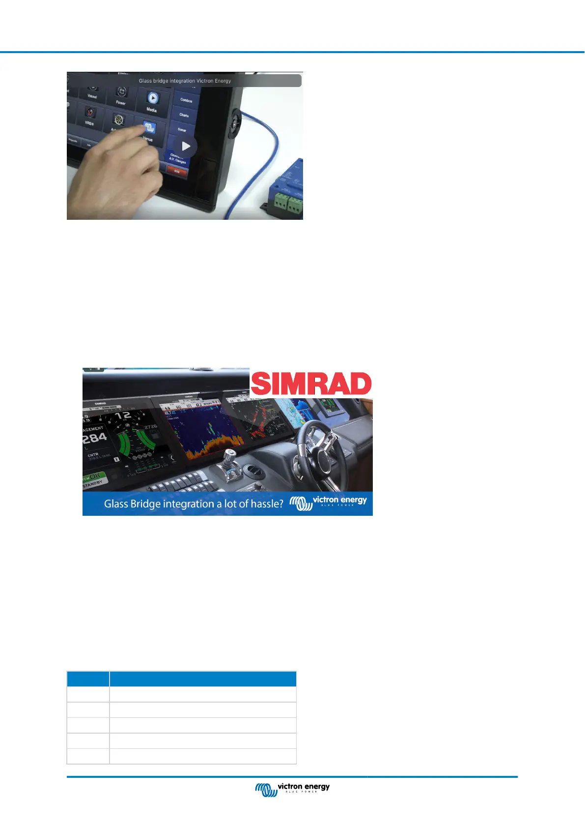
3. Go to Apps on the MFD and then select the Victron Energy logo, which will appear after a few seconds
4. And...you're done. All information can now be viewed on one screen, which is:
DC loads, Battery information, Shore power connection, Solar production, AC loads, Inverter and Generator control and the
option to open the Remote Console
This video shows the exact steps:
13.4.7. NMEA 2000
Besides connecting over ethernet, a Navico MFD can also be connected to the Victron system using NMEA 2000. If you’re new to
NMEA 2000 & Victron, start with reading theNMEA 2000 & MFD integration guide.
The MFD can be configured easily to display the data from the GX device. There is no need to change any instance.
To setup the data sources on the MFD, go to Settings > Network > Sources > Advanced.
13.4.8. Generic and supported PGNs
To setup the data sources on the Navico MFD, go to Settings > Network > Sources > Advanced.
The following Victron related PGNs are supported:
PGN Description
127505 Fluid level (tanks)
127506 DC Detailed Status (State-of-charge, Time-to-go)
127507 Charger status
127508 Battery Status (Battery Voltage, Battery Current)
127509 Inverter status
Color Control GX Manual
Page 79 Marine MFD integration by App
 Loading...