Do you have a question about the Victron energy Phoenix 12/800 and is the answer not in the manual?
| Model | Phoenix 12/800 |
|---|---|
| Input Voltage | 12V |
| Output Power | 800VA |
| Peak Power | 1600 W |
| Transfer Time | 20 ms |
| Output Voltage | 230V |
| Output Frequency | 50Hz |
| DC Input Voltage Range | 9.5 - 17 V |
| Protection | Output short circuit, Over temperature |
| Operating Temperature | -20°C to +50°C |
Covers warnings on electric shock, product servicing by qualified personnel, and grounding requirements.
Details safe operating environments, ventilation needs, and user restrictions for safe appliance use.
Describes connectivity options for computers, smartphones, and tablets via the VE.Direct port.
Lists configurable parameters like voltage, frequency, ECO mode, and monitoring capabilities.
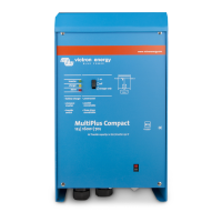
Highlights proven reliability, high start-up power for demanding loads, and ECO mode functionality.
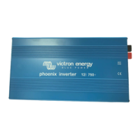
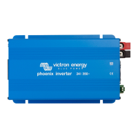
Explains the remote on/off connector and the LED indicators for operation status and protections.
Mentions the automatic transfer switch recommendation and available output socket types.
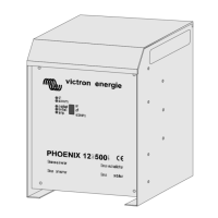
Describes various mounting positions including ceiling, base, vertical wall, and horizontal wall mounting.
Details conditions for optimal operation: avoid water, direct sunlight, and ensure adequate ventilation.
Specifies required battery capacity, internal DC fuse ratings, and recommended DC cable cross-sections.
Provides guidance on the minimum cross-section for the earth conductor connecting the chassis to ground.
Instructs users not to connect the inverter output to another AC source like a wall outlet or generator.
Explains how to connect the inverter's neutral output to the chassis/ground for specific regulations.
Details how to connect a remote on/off switch or wire to the ignition contact for automotive use.
Describes configuring the inverter using a computer or mobile devices via VE.Direct or Bluetooth dongle.
Explains Green and Red LED patterns for status and warnings, with troubleshooting steps for each.
Describes how ECO mode reduces power consumption by switching to standby when no load is detected.
Details overload, low/high battery voltage, temperature, and DC ripple protections and automatic restarts.
Presents key technical data including continuous and peak power, voltage ranges, efficiency, and operating temperatures.
Details material, battery connection, cable sizes, AC outlets, protection category, weight, dimensions, and compliance standards.
Continues detailed technical data for various models, including zero-load power and protection keys.
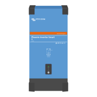
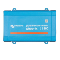
Illustrates the front and rear panels of the inverter, showing ports and indicators.
Provides visual guides for mounting the inverter vertically or horizontally on a wall or surface.
Detailed instructions and illustrations for connecting the inverter neutral to the protective earth.
Provides a table to determine the correct earth conductor cross-section based on battery connection size.