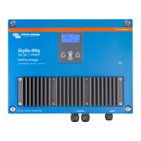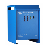
Do you have a question about the Victron energy Skylla-i 24/80 and is the answer not in the manual?
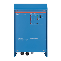
| Input Voltage | 180 - 265 VAC |
|---|---|
| Output Voltage | 24 VDC |
| Output Current | 80 A |
| Battery Type | Lead-acid, Lithium-ion |
| Operating Temperature | -20°C to +60°C |
| Protection | Overtemperature, Reverse polarity |
General safety information and warnings for product usage.
Instructions and precautions for product installation.
Guidelines for safely transporting and storing the product.
Guidance on selecting a mounting location and wiring the charger.
Instructions for grounding the charger according to safety standards.
Procedures and recommendations for connecting batteries.
Specific instructions for connecting the starter battery.
Step-by-step guide for connecting batteries safely.
Step-by-step guide for disconnecting batteries safely.
Details on connecting sensors, switches, relays, and CAN bus.
How to connect external sensors for voltage and temperature.
Instructions for connecting remote on/off and alarm relay.
Details on connecting to the CAN bus for control.
How to synchronize multiple chargers for parallel operation.
Steps to connect the AC power supply to the charger.
Overview of switches and connectors on the control board.
Explains the rotary switch for selecting battery types.
Details the function of the DIP switches for various settings.
Explains the operation of DIP switches DS-1 through DS-6.
How automatic equalization works and its parameters.
Using potentiometers for manual current and voltage adjustments.
Setting the charger to operate as a DC power supply.
How temperature affects charging and compensation.
How to manually activate the equalization mode.
Setting input current limits for mains protection.
How the charger operates during the battery charging process.
Explanation of the 7-stage charging process for lead-acid batteries.
Details the bulk charging phase.
Describes the BatterySafe mode to prevent over-gassing.
Explains the absorption charging phase.
How automatic equalization is applied after absorption.
Explains the float charging phase.
Details the storage charging phase.
Describes the weekly refresh cycle for batteries.
Explanation of the 4-stage charging for LiFePo4 batteries.
Details the bulk charging phase for LiFePo4.
Explains the absorption phase for LiFePo4.
Details the storage phase for LiFePo4.
Describes the weekly refresh cycle for LiFePo4.
Common issues and their potential causes and solutions.
Explains various error codes shown on control panels.
Details about the charger's physical enclosure and materials.
Lists safety and emission standards the product complies with.
General meaning of LED states (on, blinking, off).
Specific LED patterns indicating fault conditions.
