66550033-EN - V6.1 - 15/08/20
- 31 -
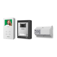
ESVK/6388 Series “2 wire Bus” videokit
ESVK/6388 Series - Installation handbook
POWER SUPPLY
To give power supply to the module
connect one of the inbuilt IDC male
connector
I
to the IDC male connector
of the camera unit module through the
at cable provided. A further buttons
expansion module can be connected to
the free IDC male connector of the pre-
vious expansion module (Fig. 3).
Art.CFL45
45 cm lenght at cable
(to be ordered separately)
Art.CFL17
17 cm lenght at cable
(Supplied)
OR
Fig. 3
SW1 SETTINGS
ALI
STEEL
MATTE
HIGH BRASS
Made in Italy
P1
EXPANSION BUTTONS
PUSH BUTTONS CONFIGURATION
MAX VALUES FOR ART:
RIGHT
SIDE
STANDARD
SW1
TRADE
36 - 40
31 - 35
26 - 30
21 - 25
16 - 20
11 - 15
6 - 10
1 - 5
LEFT
SIDE
36 - 40 n=35
31 - 35 n=30
26 - 30 n=25
21 - 25 n=20
16 - 20 n=15
11 - 15 n=10
6 - 10 n=5
1 - 5 n=0
R
L
40
39
38
37
36
35
34
33
32
31
30
29
28
27
26
25
24
23
22
21
20
19
18
17
16
15
14
13
12
11
10
9
8
7
6
5
4
3
2
1
4045 4045D
4044 4044D
4043 4043D
4042 4042D
1+n
2+n
3+n
4+n
5+n
B A
J2
B A
J1
EXPANSION BUTTONS
Left position = TRADE
Trade button connection related to push button
no.1 (only if SW1 is swithed on Trade side).
ALI
STEEL
MATTE
HIGH BRASS
Made in Italy
P1
EXPANSION BUTTONS
PUSH BUTTONS CONFIGURATION
MAX VALUES FOR ART:
RIGHT
SIDE
STANDARD
SW1
TRADE
36 - 40
31 - 35
26 - 30
21 - 25
16 - 20
11 - 15
6 - 10
1 - 5
LEFT
SIDE
36 - 40 n=35
31 - 35 n=30
26 - 30 n=25
21 - 25 n=20
16 - 20 n=15
11 - 15 n=10
6 - 10 n=5
1 - 5 n=0
R
L
40
39
38
37
36
35
34
33
32
31
30
29
28
27
26
25
24
23
22
21
20
19
18
17
16
15
14
13
12
11
10
9
8
7
6
5
4
3
2
1
4045 4045D
4044 4044D
4043 4043D
4042 4042D
1+n
2+n
3+n
4+n
5+n
B A
J2
B A
J1
EXPANSION BUTTONS
Right position = STANDARD
Standard matrix call buttons (default).
J2 AND J1 BACKLIT LEDS SETTINGS
USING WITH ART.4284, ART.4284X OR ART.4533
DEFAULT SETTING
J2 J1
B A B A
USING WITH ART. 4384 OR
ART. 4384X
AND ONE SINGLE
EXPANSION BUTTON MODULE
J2 J1
B A B A
USING WITH ART. 4384 OR
ART. 4384X AND
A COUPLE
EXPANSION BUTTON MODULES
1
2
Expansion button module 1
J2 J1
B A B A
Art.4384 - Art.4384X
Expansion button module 2
J2 J1
B A B A
NOTE: to connect more than 2 expansion button modules,
please refer also to the installation diagrams.
HOW TO REMOVE/INSERT THE CARD NAME HOLDER
• To avoid damage to the module front plate, mask the side that
will be in contact with the screwdriver blade;
• Insert the screwdriver (at side) into the card-holder hole as
shown in Fig. 4;
• Move the screwdriver to the left as shown in Fig. 5 to extract
the card name holder;
• Edit the card name then replace it inside the holder and ret:
insert the holder inside its housing from the left or right side
then push the other side until it clips into place.
Fig. 4 Fig. 5
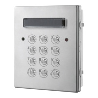
Art.4042 .. 4045 Single row button expansion modules
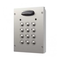
Art.4042D .. 4045D Double row button expansion modules
 Loading...