10
INDUCTION LOOP GUIDE
Induction Loop Guide EN-UK - V.1.1 - 19/10/16
Fig.15Fig.14
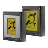
red speaker wires
scotchlok™ 3 way
butt connector
with transparent
side facing up
red wire from
female bullet
connector cable
wires fed into
connector barrels
8. Repeat steps 6 - 7 with the Blue speaker wires and the Blue female bullet wire.
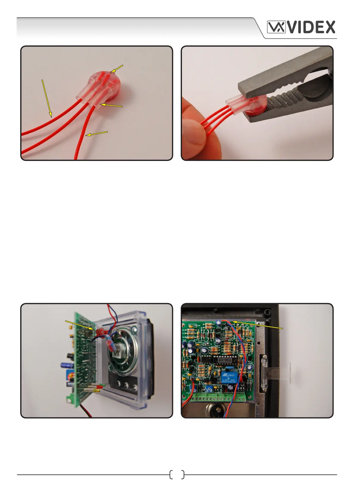
9. Once both butt connectors have been crimped replace the wire assembly back into the front
plastic, as shown in Fig.16.
10. Fold the Red/Blue female connector cable over the top side of the speaker pcb so that when the
speaker pcb sits in position on the front speaker plastic the Red/Blue connector cable runs from
the top of the speaker pcb down along the top side of the pcb, as shown in Fig.17.
11. Replace the top covering speaker plastic and fit the four M3x12 fixing screws and tighten firmly
into place, as shown in Fig.18.
12. After the top covering speaker plastic has been fitted back into position the Red/Blue female
connector cable should be trailing out from the gap of the top covering plastic just above the
terminal connections, as shown in Fig.19.
Fig.17Fig.16
Fig.14
crimped red/blue
connector wires
tucked in between
the speaker pcb
and front plastic
red/blue connector
wires folded over
the top side of the
speaker pcb
 Loading...