7
INDUCTION LOOP GUIDE
Induction Loop Guide EN-UK - V.1.1 - 19/10/16
9. Once the three Red wires are in position use a pair of pliers and place them over the red cap of
the butt connector and transparent side and apply pressure to crimp the wires into place, as
shown in Fig.5. (When crimping the wires into the butt connector check that the wires are firmly
held in position and do not slip out of the barrels).
10. Repeat steps 6 - 9 with the Blue speaker wires and the Blue female bullet wire.
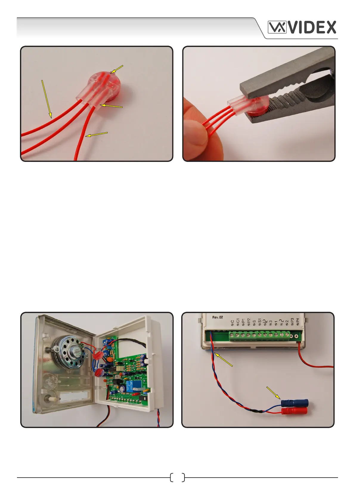
11. Once both butt connectors have been crimped tighten up the pcb screw to secure the speaker
pcb back onto the back plastic. Replace the wire assembly back into the back plastic as well,
as shown in Fig.6. (There is enough room between the speaker pcb and the front metal fascia to
accommodate the wires. When fitting to a 4K series camera module care should be taken when
manoeuvring the wire assembly to avoid obstructing the camera lens).
12. Finally clip the front metal fascia back onto the back plastic. The Red/Blue female connector
cable should now be trailing out of the bottom corner of the 4K speaker module, as shown in
Fig.7.
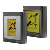
Fig.4
red speaker wires
scotchlok™ 3 way
butt connector
with transparent
side facing up
red wire from
female bullet
connector cable
wires fed into
connector barrels
Fig.5
Fig.6 Fig.7
red/blue female connector cable
trailing out the bottom of the 4K
series speaker module
 Loading...