8
INDUCTION LOOP GUIDE
Induction Loop Guide EN-UK - V.1.1 - 19/10/16
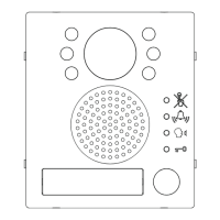
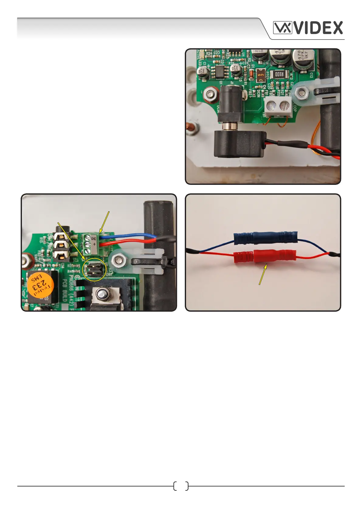
13. Next take the 12Vdc power cable and plug
it into the power plug-in terminal at the
bottom of the Induction Loop, as shown in
Fig.8.
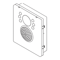
14. Next take the Red/Blue male connector
cable and connect it into the terminal block
at the top of the Induction Loop (the Red
wire connects into the +pos termnial and the
Blue wire connects into the GND terminal)
and remove both HDR1 jumpers, as shown
in Fig.9.
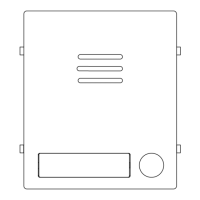
15. Finally clip the Red male/female connectors
and the Blue male/female connectors
together as shown in Fig.10.
Fig.8
Fig.9
Fig.10
blue wire into the GND terminal
red wire into the + terminal
red/blue male and female
bullet connectors plugged
in together
remove HDR1 jumpers
 Loading...